
Cold rolling forming machine and U-shaped suspension arm plate production and manufacturing method

A forming machine, U-shaped technology, applied in forming tools, manufacturing tools, metal processing equipment, etc., can solve the problems of U-shaped boom plate shape change, insufficient plastic deformation, small forming work absorption, etc., to maintain rolling Stability, increase the amount of plastic deformation, the effect of inhibiting stress release

Pending Publication Date: 2022-06-03
南京图信新材料科技有限公司
View PDF0 Cites 0 Cited by
  • Summary
  • Abstract
  • Description
  • Claims
  • Application Information

AI Technical Summary

Problems solved by technology

[0002] The cold rolling forming machine is a kind of equipment for cold rolling steel into a certain shape. The U-shaped boom is in production. The space between the racks is large and the rebound time of the transverse bending is long. The elastic relaxation in the longitudinal direction will cause the absorption of forming work. The problem of insufficient plastic deformation cannot be adjusted to a certain extent according to the change of material properties and thickness of the plate, and when the continuous rolling is completed, the residual tensile stress at different points on the same cross-section in the longitudinal direction is different. Similarly, the longitudinal tensile stress and transverse stress mutually restrict each other to form a balanced state. When the section steel is cut off, the stress balanced state is broken, which will cause new springback and cause the shape of the U-shaped boom plate to change, so there are defects in use.

Method used


Image

  • Cold rolling forming machine and U-shaped suspension arm plate production and manufacturing method
  • Cold rolling forming machine and U-shaped suspension arm plate production and manufacturing method
  • Cold rolling forming machine and U-shaped suspension arm plate production and manufacturing method

Examples


Embodiment Construction

[0031] The technical solutions in the embodiments of the present invention will be clearly and completely described below. The embodiments of the present invention, and all other embodiments obtained by those of ordinary skill in the art without creative work, fall within the protection scope of the present invention.

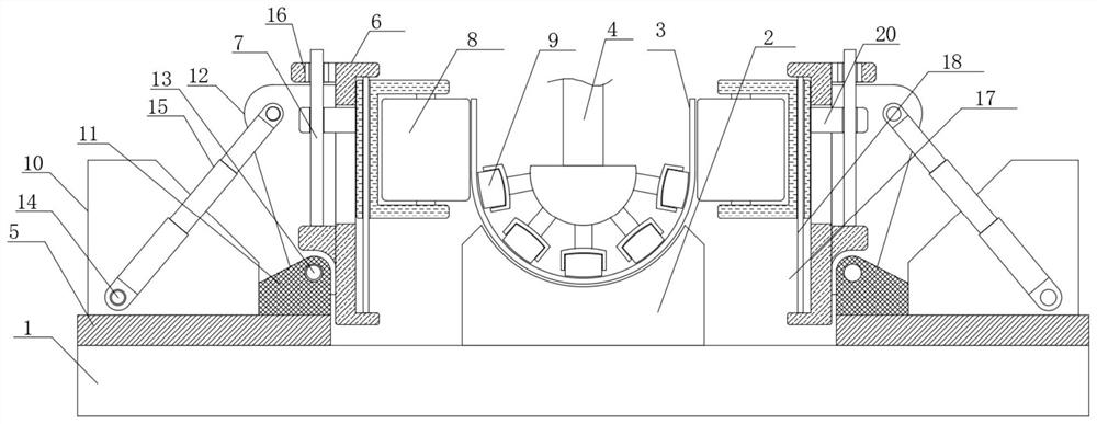
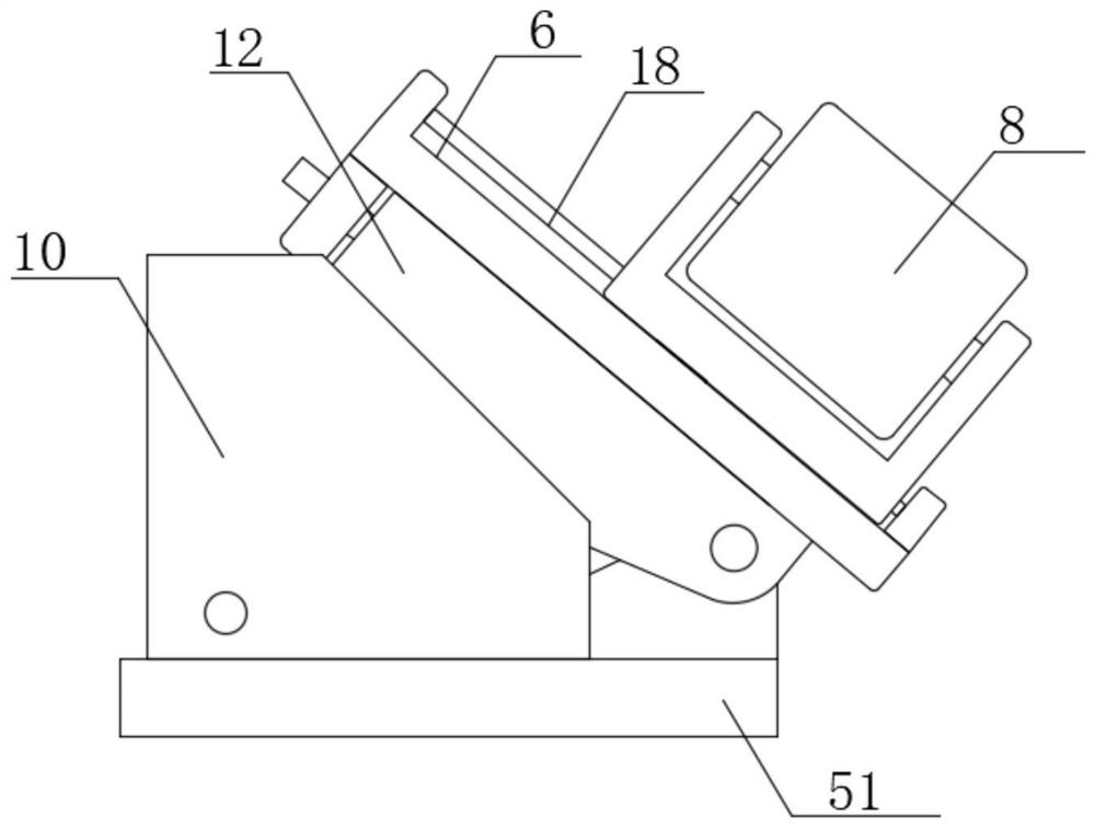
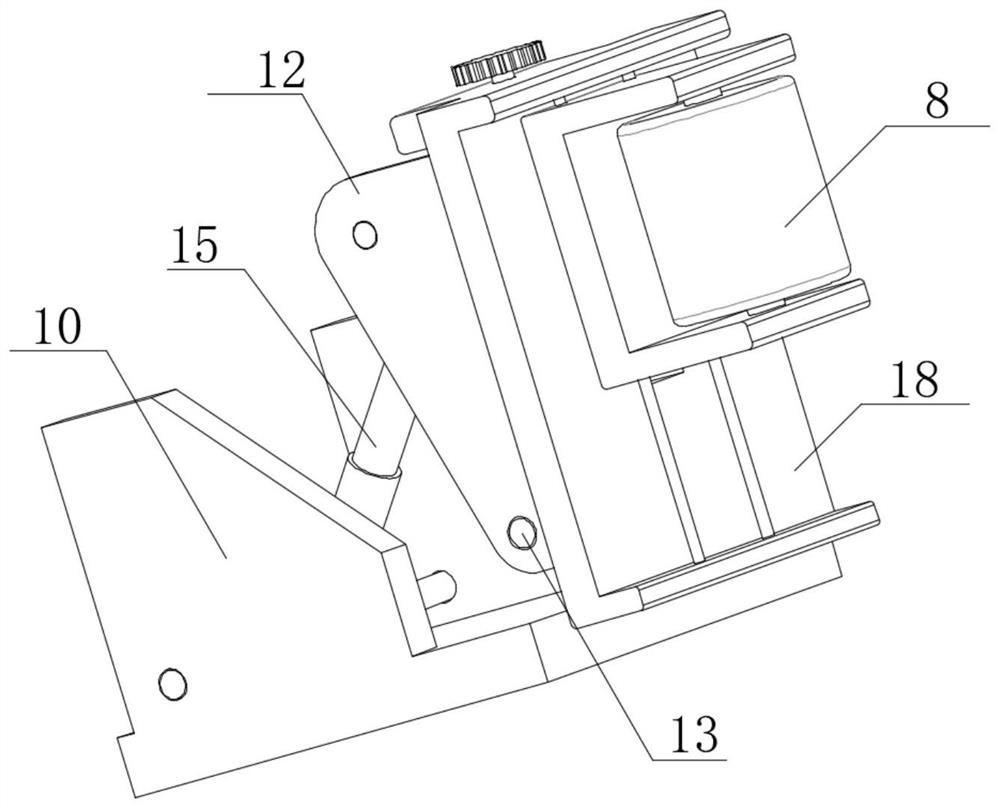
[0032] see Figure 1-5 , the present invention provides a cold rolling forming machine: the cold rolling forming machine comprises:

[0033] Finishing table 1, the center of the upper end of the finishing table 1 is provided with a lower mold 2, a plate 3, the plate 3 is arranged on the upper end of the lower mold 2, and the plate 3 is located on one side of the lower mold 2. The upper end is provided with an upper mold 4, a support component, a support The assembly is arranged on the upper end of the finishing table 1 near the two sides of the lower die 2, and the support assembly includes a support seat 5 and a movable plate 6, the upper end of the lower die...


PUM


Abstract

The invention relates to the field of forming equipment, in particular to a cold rolling forming machine and a U-shaped suspension arm plate manufacturing method.The cold rolling forming machine comprises a finishing workbench, a lower die and a plate are arranged in the center of the upper end of the finishing workbench, the plate is arranged at the upper end of the lower die, and an upper die is arranged at the position, located at the upper end of one side of the lower die, of the plate. The method shortens the elastic recovery time, prolongs the rolling time, has good effects of inhibiting stress release, improving plastic deformation and keeping rolling stability, can adapt to material performance changes in a certain range through bend angle adjustment, eliminates internal stress generated by strong rolling after normalizing treatment, and improves the rolling quality. Thermal deformation caused by heat treatment is treated in the finishing section, and the section, longitudinal bending and transverse bending of the profile are further corrected, so that the internal stress of the material of the forming section is effectively controlled, the end springback caused by placement after cutting is reduced, and the new process can meet the production of the U-shaped suspension arm.

Description

technical field [0001] The invention relates to the field of forming equipment, in particular to a cold rolling forming machine and a manufacturing method for a U-shaped boom plate. Background technique [0002] Cold-rolling forming machine is a kind of equipment that cold-rolls steel into a certain shape. The U-shaped boom is in production, and the springback time of transverse bending is long when the rack spacing is large, and the elastic relaxation in the longitudinal direction is too large, which will cause the absorption of forming work. Small, insufficient plastic deformation, it cannot be adjusted to a certain extent according to the change of material properties of the plate and the change of plate thickness, and when the continuous rolling is completed, the residual tensile stress at different points on the same cross section in the longitudinal direction is not the same. In the same way, the longitudinal tensile stress and the transverse stress mutually restrict e...

Claims


Application Information

Patent Timeline
Patent Type & Authority Applications(China)
IPC IPC(8): B21D5/08B21D37/16C21D1/28
CPCB21D5/08B21D37/16C21D1/28
Inventor 张顺生许德根项小庆周昌福朱发林刘峰岭倪军
Owner 南京图信新材料科技有限公司
Learn More