Machining and positioning tool for side face hole of slewing bearing

A technology of slewing bearing and positioning tooling, which is applied in positioning devices, supports, metal processing equipment, etc., can solve the problems of clogging and reserved groove cleaning, low processing efficiency of slewing bearings, low continuous operation efficiency, etc. The convenience of clearing blockage, avoiding too long cleaning time, and reducing the effect of post-processing workload

Active Publication Date: 2022-06-03
招远市金环回转支承有限公司
View PDF8 Cites 0 Cited by
  • Summary
  • Abstract
  • Description
  • Claims
  • Application Information

AI Technical Summary

Problems solved by technology

[0003] The existing slewing bearing side hole processing positioning tool, in the process of use, usually put the slewing bearing on the top of the positioning work, cooperate with the positioning splints on both sides to realize fixed clamping, and cooperate with the drill pipe and cutting fluid for continuous drilling when drilling. For the drilling process of medium and large-sized slewing bearings, the actual diameter of the hole is large, and the amount of waste generated during the drilling process is large, and the actual waste volume is large and the structure is strong. During the continuous drilling process, the splashed waste is everywhere. Scattering, in which waste materials are easily accumulated in the side holes adjacent to the drilling position, and the waste materials are easy to jam after falling in. It is difficult to actually clean the side holes. In order to ensure that the drill pipe does not damage the positioning work during drilling, usually Set up a reserved slot at the punching position of the positioning tool. The reserved slot also accumulates a large amount of waste after the drilling is completed. When continuously processing multiple sets of slewing bearings, the reserved slot needs to be cleaned in time to ensure that the reserved slot has sufficient It is troublesome to actually complete the internal cleaning of side holes and the cleaning of reserved grooves, the cleaning time is long, and the continuous operation efficiency is low. The actual processing efficiency of large-scale slewing bearings is low, and the use effect is not good.

Method used


Image

  • Machining and positioning tool for side face hole of slewing bearing
  • Machining and positioning tool for side face hole of slewing bearing
  • Machining and positioning tool for side face hole of slewing bearing

Examples


no. 1 example

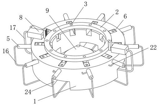
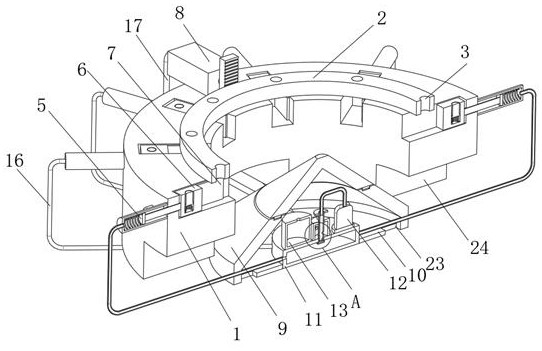
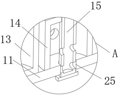
[0022] The first embodiment: as figure 1 , figure 2 , image 3 , Figure 4 and Figure 5 As shown, the slewing bearing 2 is placed on the top surface of the mounting base 1, and the hydraulic pump 12 is started. As the hydraulic pump 12 enters the No. 2 distribution sleeve 14, the internal oil pressure of the No. 2 distribution sleeve 14 increases, so that the The pressure oil enters the positioning mechanism 8 through the No. 2 pipe 17, and the positioning mechanisms 8 on both sides act simultaneously, so that the slewing bearing is fixedly clamped between the two sets of positioning mechanisms 8. After the drilling is completed, the telescopic rod 20 is activated to make the telescopic The rod 20 pushes the adjustment mechanism 15 down, so that the No. 2 hole 155 on the adjustment mechanism 15 moves down from the through hole 25 to the inside of the No. 1 distribution sleeve 11. At this time, the hydraulic pump 12 simultaneously supplies the No. 1 distribution sleeve 11 ...

no. 2 example

[0034] Second embodiment: as figure 1 , figure 2 , Figure 4 and Figure 10 As shown, during the continuous machining of large batches of slewing bearings, as the drilling arm drills along the top surface of the slewing bearing 2, a large amount of scrap is sputtered out and falls on the outer surface of the guide mechanism 9, and with the large amount of cutting When the liquid is ejected, part of the cutting fluid flows into the outer surface of the guide mechanism 9 , and the cutting along the inclined downward flow of the guide mechanism 9 flows down with the falling scrap, and the cutting fluid mixed with the scrap flows into the mounting seat 1 through the guide mechanism 9 In the side groove 24, and with the continuous drilling work, the cutting fluid used in large quantities and sprayed continuously slides down to the side groove 24 along the guide mechanism 9, and the cutting fluid flowing down from a high place by gravity at this time is The bottom gathers into a...


PUM


Abstract

The invention belongs to the technical field of slewing bearing machining equipment, and discloses a slewing bearing side face hole machining positioning tool which comprises a mounting base and a slewing bearing, a reserved groove is formed in the top face of the mounting base, a mounting mechanism is fixedly mounted on the outer surface of the mounting base, and a pushing mechanism is arranged at the inner end of the mounting mechanism. The pushing mechanism is located in the reserved groove. By additionally arranging the first distribution sleeve and the adjusting mechanism, after drilling is completed, pressure oil of a hydraulic pump is guided into the first distribution sleeve by controlling the adjusting mechanism, so that the multiple sets of pushing mechanisms slide and push out waste materials in the preformed grooves, and automatic cleaning of the waste materials on the inner surfaces of the multiple sets of preformed grooves is achieved; therefore, it is guaranteed that the reserved groove has enough space during subsequent machining, accumulated waste is prevented from influencing stable drilling of the drill rod, cleaning is convenient and rapid, the situation that cleaning time is too long is avoided, the preparation time for replacing a next set of slewing bearings is shortened, and the machining efficiency of large-batch slewing bearings is improved.

Description

technical field [0001] The invention belongs to the technical field of slewing bearing processing equipment, in particular to a slewing bearing side hole processing and positioning tool. Background technique [0002] The slewing bearing is a new type of mechanical parts. It consists of inner and outer rings, rolling elements, etc. The slewing bearing is a large bearing that can withstand comprehensive loads. It can bear large axial and radial loads and overturning moments at the same time. With the continuous development of the construction machinery manufacturing industry, the demand for special large-scale and super-large slewing bearings is increasing day by day, and the precision requirements for them are also getting higher and higher. When drilling side holes for slewing bearings, positioning tooling is often used. The punch arm is complete. [0003] In the existing slewing bearing side hole processing and positioning tool, during use, the slewing bearing is usually p...

Claims


Application Information

Patent Timeline
Patent Type & Authority Applications(China)
IPC IPC(8): B23Q3/00B23Q11/10
CPCB23Q3/00B23Q11/10Y02P70/10
Inventor 柳耀国王春民
Owner 招远市金环回转支承有限公司
Why Eureka
Try Eureka