
Concrete 3D printing material based on section molding and 3D printing manufacturing method

A 3D printing and manufacturing method technology, applied in the direction of manufacturing tools, additive processing, ceramic molding machines, etc., can solve the difficulties of adding steel bars, the impact and mechanism of action are not completely clear, and the uncertainty of the engineering application of concrete 3D printing manufacturing, etc. problems, to achieve the effect of ensuring printing efficiency, improving printing efficiency, and ensuring long-term stability

Active Publication Date: 2022-06-03
中路高科交通检测检验认证有限公司
View PDF7 Cites 0 Cited by
  • Summary
  • Abstract
  • Description
  • Claims
  • Application Information

AI Technical Summary

Problems solved by technology

There are several problems in this manufacturing method: (1) It is difficult to add steel bars in the printing manufacturing process
At present, the influence and mechanism of the anisotropy of concrete manufactured by 3D printing on the structural performance of components are not completely clear.
Due to the existence of the above problems, there are many problems in the mechanical properties of the components manufactured by concrete 3D printing. As a result, it is difficult to integrate into the design and construction standard system of a large number of concrete structures such as existing buildings and bridges. application brings uncertainty
Therefore, the large-scale application of concrete 3D printing manufacturing based on the layer-by-layer superposition process is not mature enough and needs further research
[0004] Aiming at the inconvenience and defects of the above-mentioned existing concrete 3D printing manufacturing technology, this application creates a new concrete 3D printing material and 3D printing material based on section shaping The manufacturing method enables it to obtain a high fluidity and fast-setting printing material by improving the characteristics of the printing material, so that it can not only meet the needs of filling densely reinforced reinforcement cages, but also meet the rapid setting of concrete, and achieve the cross-sectional modeling-based The purpose of rapid concrete printing can also ensure the long-term stability of the concrete structure, overcome the shortcomings of existing concrete 3D printing, and become the goal that the industry needs to improve.

Method used

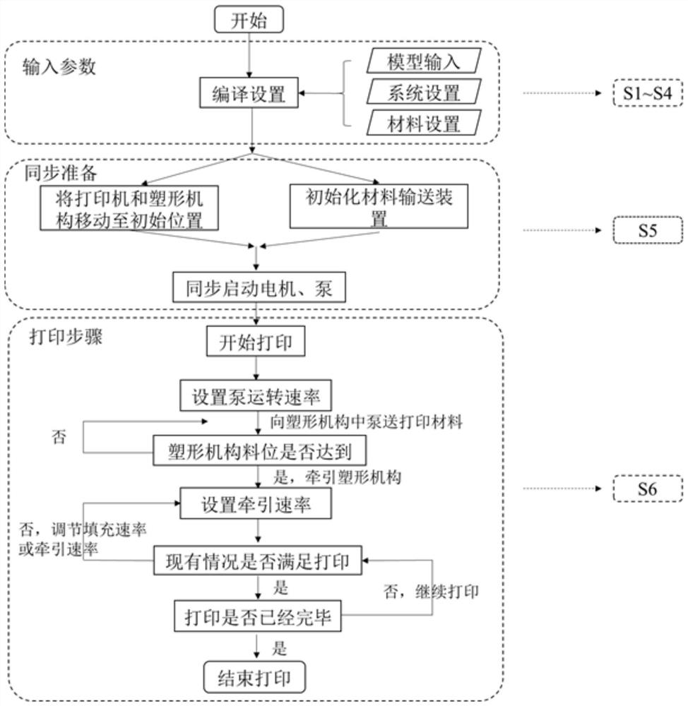

Image

  • Concrete 3D printing material based on section molding and 3D printing manufacturing method
  • Concrete 3D printing material based on section molding and 3D printing manufacturing method

Examples


Embodiment 1

[0061] The cement-based retarding mixture of this embodiment includes aggregates, cementitious materials, fibers, a first rheology-modifying component, and water.

[0062] The aggregate in this embodiment is 0.63mm-2.36mm continuously graded quartz sand, which accounts for 90% of the total mass of the cement-based retarding mixture.

[0063] The cementitious material in this embodiment is P.O 52.5 ordinary Portland cement, and the proportion of the cementitious material in the total mass of the cement-based retarding mixture is 8%.

[0064] The fibers in this embodiment are polypropylene fibers, and the proportion of the polypropylene fibers in the total mass of the cement-based retarding mixture is 1.2%.

[0065] The first rheology-adjusting component of this embodiment includes a polycarboxylic acid-based superplasticizer and hydroxypropyl methylcellulose ether. The proportion of the first rheology-adjusting component to the total mass of the cementitious material is 10%. ...

Embodiment 2

[0070] The cement-based retarding mixture of this embodiment includes aggregates, cementitious materials, fibers, a first rheology-modifying component, and water.

[0071] The aggregate in this embodiment is 0.63mm-2.36mm continuously graded quartz sand, which accounts for 10% of the total mass of the cement-based retarding mixture.

[0072] The cementitious material in this embodiment is P.O 52.5 ordinary Portland cement, and the proportion of the cementitious material in the total mass of the cement-based retarding mixture is 70%.

[0073] The fibers in this embodiment are steel fibers, and the proportion of the steel fibers in the total mass of the cement-based retarding mixture is 3%.

[0074] The first rheology-adjusting component of this embodiment includes polycarboxylic acid-based superplasticizer and hydroxyethyl cellulose ether. The proportion of the first rheology-adjusting component to the total mass of the cementitious material is 10%.

[0075] The setting adjus...

Embodiment 3

[0079]The cement-based retarding mixture of this example includes aggregates, cementitious materials, fibers, rheology-modifying components, and water.

[0080] The aggregate in this embodiment is 0.63mm-2.36mm continuously graded quartz sand, which accounts for 50% of the total mass of the cement-based material.

[0081] The cementitious material in this embodiment is P.O 52.5 ordinary Portland cement, and the proportion of the cementitious material in the total mass of the cement-based material is 40%.

[0082] The fibers in this embodiment are polyvinyl alcohol fibers, and the proportion of the polyvinyl alcohol fibers in the total mass of the cement-based material is 2.5%.

[0083] The first rheology-adjusting component in this embodiment includes a polycarboxylic acid-based superplasticizer, hydroxypropyl methylcellulose ether and nano-modified clay. The proportion of the first rheology-adjusting component to the total mass of the cementitious material is 1.5%.

[0084]...


PUM


Abstract

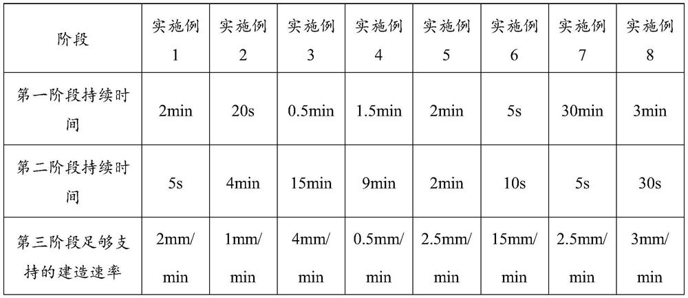
The invention discloses a concrete 3D printing material based on section molding and a 3D printing manufacturing method, and belongs to the technical field of concrete 3D printing manufacturing. The concrete 3D printing material comprises a cement-based delayed coagulation mixture and a coagulation adjusting component, the cement-based delayed coagulation mixture is composed of aggregate, a cementing material, fibers, a first rheological adjusting component and water, the coagulation adjusting component is composed of an early strength-delayed coagulation component and a second rheological adjusting component, and the cement-based delayed coagulation mixture and the coagulation adjusting component are mixed before use. The 3D printing material with three-stage development of material performance of a first stage with high fluidity, a second stage with rapid condensation and a third stage with rapid strength increase is formed. Through the first stage of high fluidity, reinforcement cage filling can be achieved; in the second stage of rapid condensation, rapid movement of the section molding template can be realized; and in the third stage, the long-term stability of the concrete is guaranteed, and the technical defects that in an existing layer-by-layer stacking 3D printing mode, steel bars are difficult to add, cold joints are formed, and anisotropy is caused are effectively overcome.

Description

technical field [0001] The invention relates to the technical field of concrete 3D printing manufacturing, in particular to a concrete 3D printing material and a 3D printing manufacturing method based on section molding. Background technique [0002] With the rapid development of society, the traditional manufacturing methods of concrete structures (buildings, bridges, etc.) urgently need to be transformed and upgraded to the direction of intelligence and mechanization. 3D printing technology has the characteristics of high degree of automation, one-time molding, less consumables and process loss, etc. It is an effective way to solve efficient, safe, digital, automated, and intelligent construction, and provides concrete structures (buildings, bridges, etc.) manufacturing transformation and upgrading. good opportunity. Therefore, 3D printing research based on cement-based materials is in the ascendant. [0003] At present, the concrete 3D printing manufacturing process is ...

Claims


Application Information

Patent Timeline
Patent Type & Authority Applications(China)
IPC IPC(8): C04B28/04B28B1/00B33Y10/00B33Y70/10
CPCC04B28/04B28B1/001B33Y10/00B33Y70/10C04B2111/00181C04B2201/50C04B14/06C04B16/0633C04B2103/302C04B24/383C04B22/08C04B24/10C04B24/32C04B14/48C04B24/122C04B16/0641C04B24/2641Y02W30/91
Inventor 张守祺昂源路振宝张磊杜仕朝
Owner 中路高科交通检测检验认证有限公司
Learn More