
Oil outlet control valve of electronic control oil injector

An oil control valve and electronically controlled fuel injection technology, which is applied to fuel injection devices, machines/engines, charging systems, etc., can solve the problems of decreased fuel injection accuracy, decreased oil pressure unloading speed, etc., so as to increase service life and reduce Hazardous, usefulness-increasing effects

Inactive Publication Date: 2022-06-03
吴敏
View PDF0 Cites 0 Cited by
  • Summary
  • Abstract
  • Description
  • Claims
  • Application Information

AI Technical Summary

Problems solved by technology

[0003] The existing electronically controlled fuel injector uses a solenoid valve mechanism to control the injection and stop of fuel, so the response speed of the solenoid valve is the key to determine the fuel injection performance of the fuel injector. After the conventional electronically controlled fuel injector is powered on, the ball valve Open to realize the connection of high and low pressure oil circuits, and then unload the high pressure fuel pressure. It is precisely because the high and low pressure oil circuits are directly connected that the speed of oil pressure unloading in the control chamber decreases, so that the opening of the needle valve lags behind, and the fuel injection accuracy is further improved. drop, so we propose an electronic control injector oil control valve

Method used


Image

  • Oil outlet control valve of electronic control oil injector
  • Oil outlet control valve of electronic control oil injector
  • Oil outlet control valve of electronic control oil injector

Examples


Embodiment

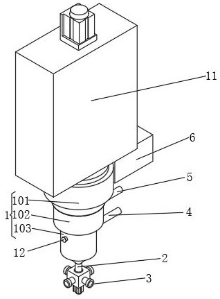
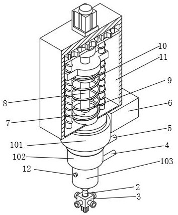
[0020] In a specific embodiment of the present invention, through the cooperative use of multiple components inside the invention, the pressure required to generate fuel injection can be injected at the correct time and the correct fuel injection quantity, and at the same time, the internal pressure of the valve body 1 can be controlled. The volume can be minimized, which improves the effect of fuel pressurization and the control of fuel injection quantity. Multiple pipelines are distributed, which increases the practicability of the oil outlet control valve. Through the setting of the oil discharge pipe 5, when the oil intake is too large, the excess fuel can be exported and recycled, which reduces the excessive fuel base. The harm to the oil outlet control valve, at the same time, through the coordinated use of the air pressure adjustment component 12, when the air pressure inside the control valve body 1 is too large, the pressure inside the control valve body 1 is reduced, ...


PUM


Abstract

The invention discloses an oil outlet control valve of an electronic control oil injector, and belongs to the technical field of fuel injection systems, the oil outlet control valve comprises a control valve body, the control valve body comprises a first valve body, a second valve body and a third valve body, the second valve body is communicated with the bottom of the first valve body, the third valve body is communicated with the bottom of the second valve body, and the first valve body is communicated with the bottom of the first valve body; the bottom of the third valve body communicates with an oil outlet head, the bottom of the oil outlet head communicates with a distribution assembly, one side of the second valve body communicates with an oil inlet pipe, one side of the first valve body communicates with an oil discharge pipe, one side of the first valve body is fixedly connected with a mounting box, and the top of the first valve body is fixedly connected with a sliding ring. And the surface of the sliding ring is slidably connected with a first moving column, the surface of the first moving column is slidably connected with a moving ring, and the top of the first valve body is fixedly connected with a height moving assembly. On the basis that oil outlet is controlled, the response time of the control valve can be shortened.

Description

technical field [0001] The invention relates to the technical field of fuel injection systems, and more particularly, to a fuel outlet control valve of an electronically controlled fuel injector. Background technique [0002] The fuel injector is a precision device with very high machining accuracy, which requires a large dynamic flow range, strong anti-clogging and anti-pollution capabilities, and good atomization performance. The fuel injector receives the fuel injection pulse signal sent by the ECU to control the fuel injection quantity. The spray characteristics of the injector include atomization particle size, oil mist distribution, oil beam direction, range and diffusion cone angle. These characteristics should meet the requirements of the diesel engine combustion system, so that the mixture formation and combustion can be perfected, and high power and thermal efficiency can be obtained. The outlet control valve in the injector is more important. [0003] The exist...

Claims


Application Information

Patent Timeline
IPC IPC(8): F02M51/00F02M51/06F02M61/10F02M61/18F02M63/00
CPCF02M51/00F02M51/0653F02M61/10F02M61/18F02M63/0017Y02T10/40
Inventor 吴敏
Owner 吴敏
Features
  • Generate Ideas
  • Intellectual Property
  • Life Sciences
  • Materials
  • Tech Scout
  • Unparalleled Data Quality
  • Higher Quality Content
  • 60% Fewer Hallucinations
Learn More