
Composite hydraulic oil cylinder of large-tonnage powder hydraulic forming machine

A technology of hydraulic cylinders and forming machines, which is applied in the direction of material forming presses, stamping machines, presses, etc., and can solve the problems of increased use costs and limited use places

Inactive Publication Date: 2022-06-03
CHANGZHOU JIUYAJIU MACHINERY MFG
View PDF0 Cites 0 Cited by
  • Summary
  • Abstract
  • Description
  • Claims
  • Application Information

AI Technical Summary

Problems solved by technology

[0005] In this way, specific requirements are placed on the height of the installation workshop and the ambient temperature of the place of use of this type of large-tonnage hydroforming equipment, the place of use is limited, and the cost of use increases

Method used


Image

  • Composite hydraulic oil cylinder of large-tonnage powder hydraulic forming machine
  • Composite hydraulic oil cylinder of large-tonnage powder hydraulic forming machine
  • Composite hydraulic oil cylinder of large-tonnage powder hydraulic forming machine

Examples


Embodiment 1

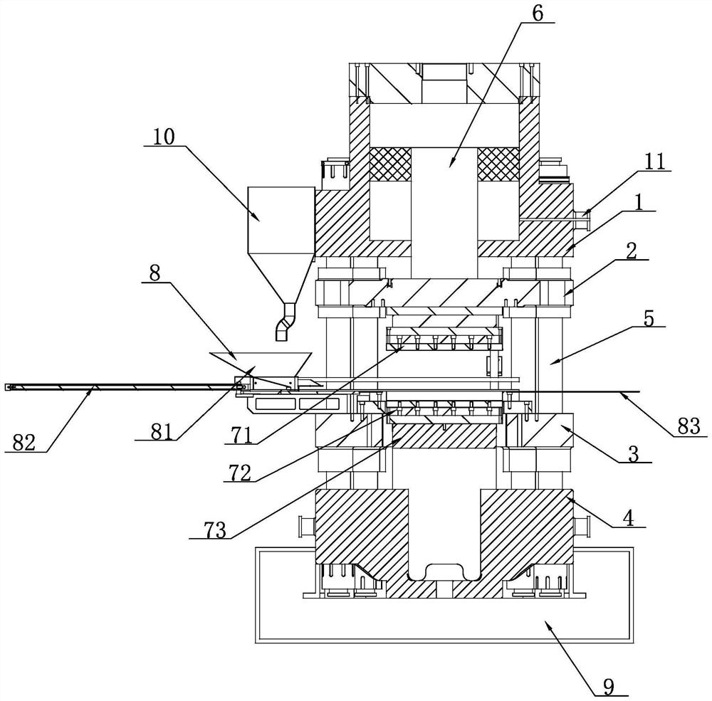
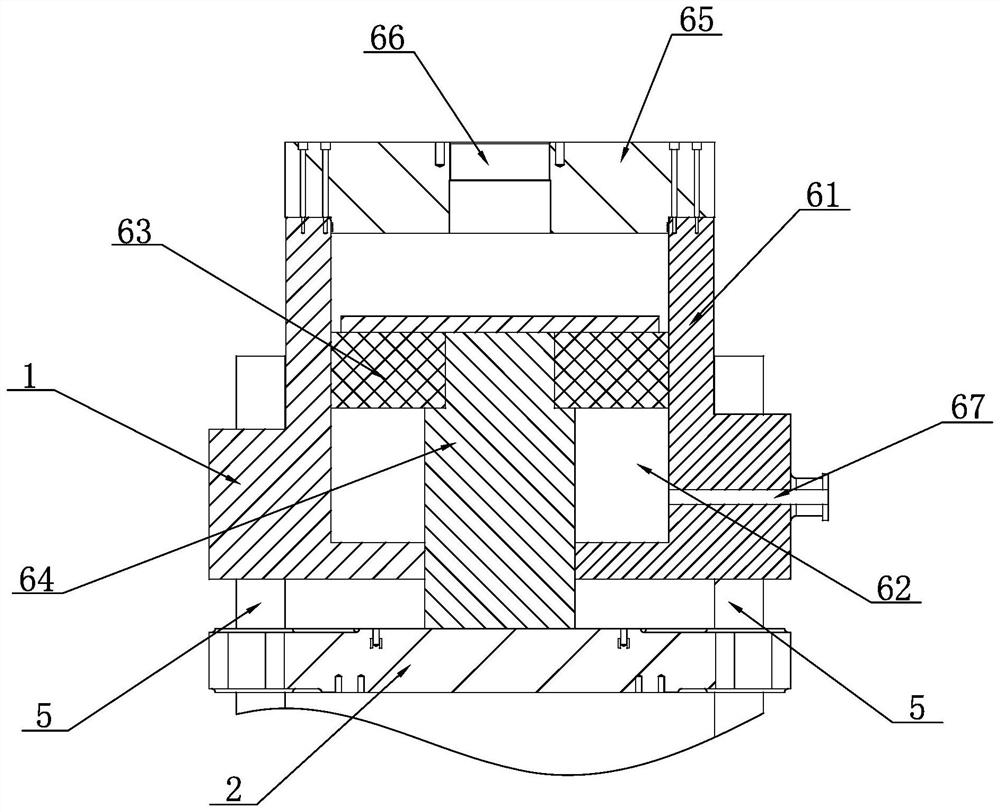
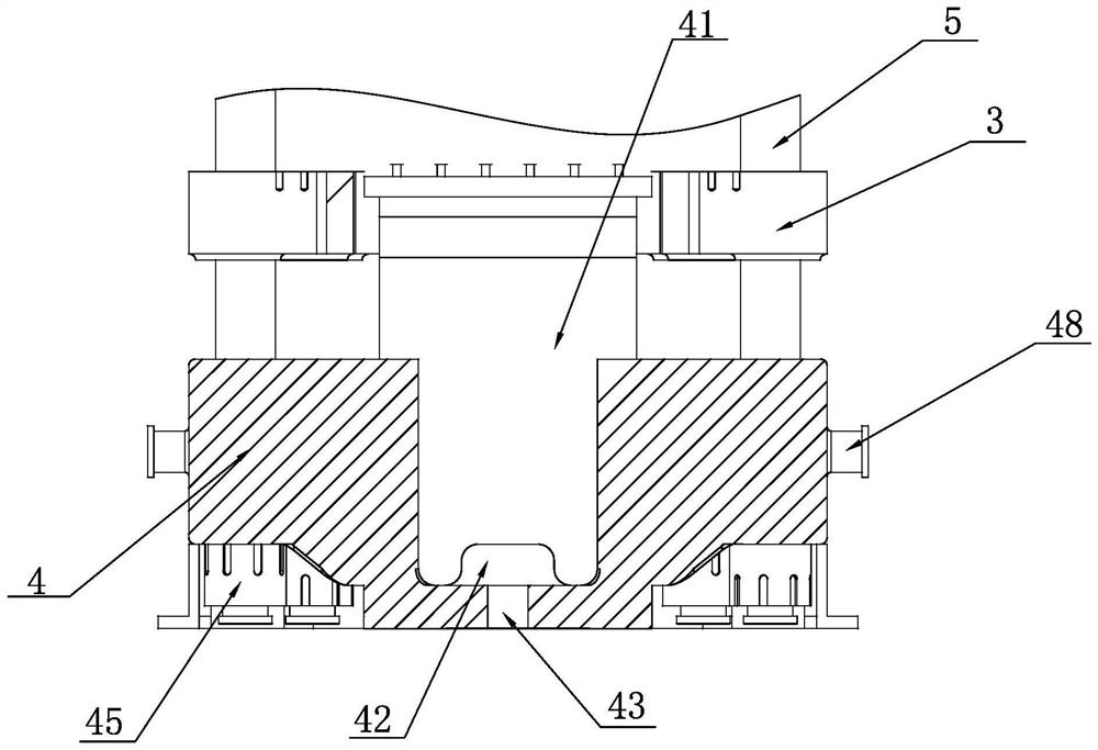
[0027] A composite hydraulic cylinder of a large-tonnage powder hydraulic molding machine, such as Figure 1-7 As shown, it includes an upper fixed plate 1, an upper moving plate 2, a lower moving plate 3, a base 4, eight columns 5, a main pressure cylinder 6, a composite molding die, a feeder 8, an oil storage tank 9 and a powder material tank 10, The eight uprights 5 are divided into four groups and are respectively arranged between the upper fixed plate 1 and the base 4, the two ends of all the uprights 5 are respectively fixed on the upper fixed plate 1 and the base 4, and the upper moving plate 2 and the lower moving plate 3 are respectively sleeved on the upper fixed plate 1 and the base 4. On the eight uprights 5, the upper moving plate 2 and the lower moving plate 3 can slide up and down along the eight uprights 5. The upper fixed plate 1 doubles as the master cylinder 61 of the main hydraulic cylinder 6, and is located in the center of the upper fixed plate 1. The pos...

Embodiment 2

[0030] Embodiment 2: Different from Embodiment 1, in order to further reduce the number of parts, the master cylinder piston 63 and the master cylinder piston rod 64 are an integrated structure; in order to further reduce the self-weight of the equipment, the master cylinder piston rod 64 and The center of the master cylinder piston 63 is provided with a weight reduction cavity 46; in order to further reduce the height of the whole machine and reduce the oil leakage path, the master cylinder block 61 and the cylinder cover plate 65 are integrated.

[0031] In order to facilitate the processing and installation of the upper fixing plate 1 , the upper lifting lugs 11 are symmetrically arranged at equal height positions on the side of the upper fixing plate 1 , and the upper moving oil holes 67 are arranged along the axis of the upper lifting lugs 11 .

[0032]This structure reduces the height of the 6,000-ton powder iso-density press molding machine to 6.43 meters, and the equipm...


PUM


Abstract

A composite hydraulic oil cylinder of a large-tonnage powder hydraulic forming machine comprises an upper fixing plate and an upper moving plate, the upper fixing plate serves as a main cylinder body of a main hydraulic cylinder, a main cylinder inner hole is formed in the center of the upper fixing plate, a main cylinder piston rod is fixedly connected with a main cylinder piston, and the lower end of the main cylinder piston rod is fixed to the upper moving plate. A pressing-down oil inlet hole is formed in the oil cylinder cover plate, an upward moving oil inlet hole is formed in the upper fixing plate, the pressing-down oil inlet hole and the upward moving oil inlet hole are both communicated with an inner hole of a main cylinder, and the pressing-down oil inlet hole and the upward moving oil inlet hole are respectively communicated with an oil supply system of a hydraulic station. The combination of the main cylinder piston and the main cylinder piston rod pushes the upper moving plate to move downwards, and the upper moving oil inlet hole is in a pressure relief state. The key technical scheme of the large-tonnage, small-sized, light and heavy energy-saving and material-saving powder hydraulic forming equipment is the structural design that the upper fixing plate and the main pressure oil cylinder are integrated, and the height and the self weight of the equipment with the same specification can be greatly reduced by adopting the scheme of the large-tonnage, small-sized, light and material-saving powder hydraulic forming equipment.

Description

Technical field: [0001] The present invention relates to forming and processing equipment for powder pressed parts, in particular to large-tonnage powder hydraulic forming equipment. Background technique: [0002] At present, with the continuous improvement of energy saving and environmental protection requirements, the size specifications of powder pressed articles using powder high pressure molding are getting larger and larger, and the application range of large powder pressed articles is more and more common, and the fields of powder pressed articles are used. With the continuous expansion, the market demand for powder pressed parts increases year by year. Although the existing tablet presses can press granular and powdery raw materials into tablets of various shapes, the operation is simple and easy to learn as long as the corresponding molds are replaced. However, the existing pressing equipment is usually a four-plate and four-column structure, that is, it includes a...

Claims


Application Information

Patent Timeline
Patent Type & Authority Applications(China)
IPC IPC(8): F15B15/14F15B15/20B30B1/32B30B11/02F16L57/02H02G3/04
CPCF15B15/1423F15B15/1447F15B15/1457F15B15/149F15B15/20B30B1/32B30B11/02F16L57/02H02G3/0493H02G3/0462
Inventor 景卫平张成方树军赵林胜
Owner CHANGZHOU JIUYAJIU MACHINERY MFG
Learn More