Open type current limiting reactor and manufacturing method thereof

A current-limiting reactor and the technology of its manufacturing method are applied in the directions of inductance/transformer/magnet manufacturing, transformer/reactor installation/support/suspension, transformer/inductor cooling, etc. Problems such as large ground area, to achieve the effect of reducing the overall weight, increasing the heat dissipation area, and saving land area

Pending Publication Date: 2022-06-03
SHANDONG HADA ELECTRIC
View PDF0 Cites 1 Cited by
  • Summary
  • Abstract
  • Description
  • Claims
  • Application Information

AI Technical Summary

Problems solved by technology

[0003] The common current-limiting reactor in the market is a closed current-limiting reactor, which is made of 0.3 aluminum soft glass fiber film wrapped round aluminum wire, two layers of glass fiber, and three layers of non-woven fabric. The process is complicated, and due to the structure Due to the limitations of the design, the heat dissipation coefficient is small, and the temperature rise is easy to be too high during the operation of the product, and because the product is wrapped with an insulating film, it is easy to break down. After the breakdown, the coil cannot be repaired, and it takes a lot of time and effort to maintain; In addition, after the product coil is coated and dipped, the overall weight and structure of the product are large, the floor area is large, and the installation method is limited.

Method used


Image

  • Open type current limiting reactor and manufacturing method thereof
  • Open type current limiting reactor and manufacturing method thereof
  • Open type current limiting reactor and manufacturing method thereof

Examples


Embodiment Construction

[0031] The principles and features of the present invention will be described below with reference to the accompanying drawings. The examples are only used to explain the present invention, but not to limit the scope of the present invention.

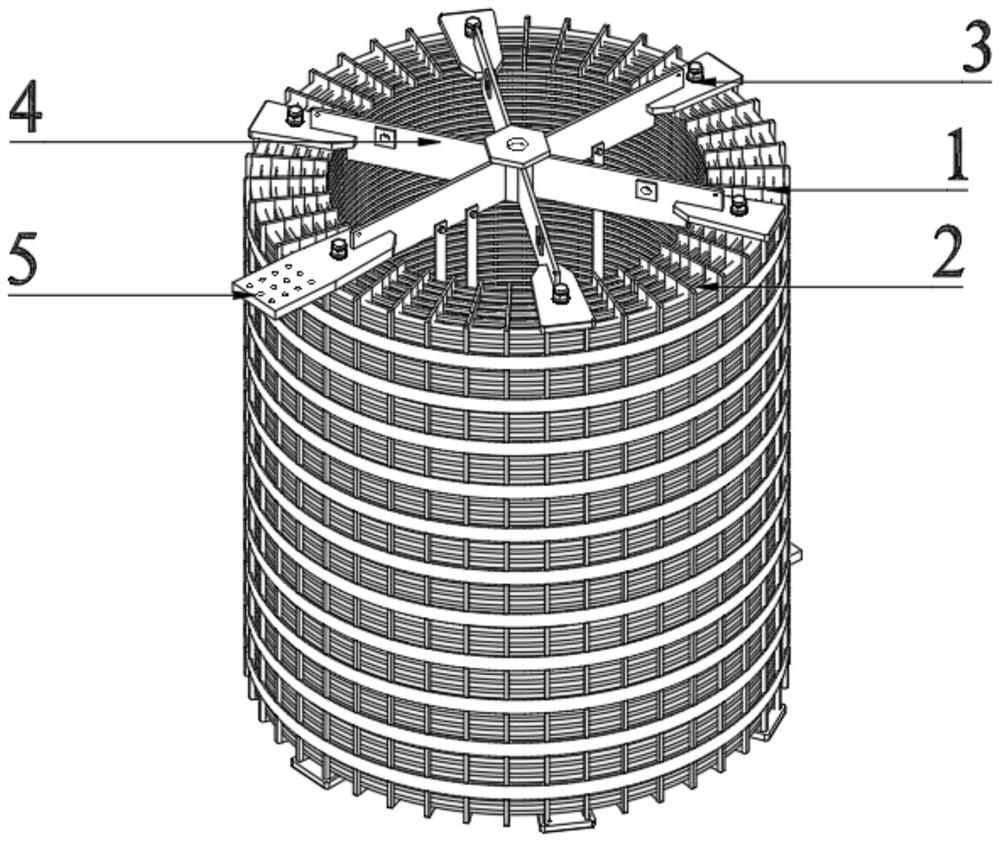
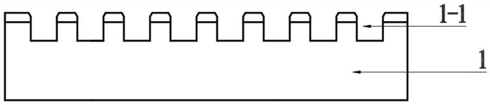
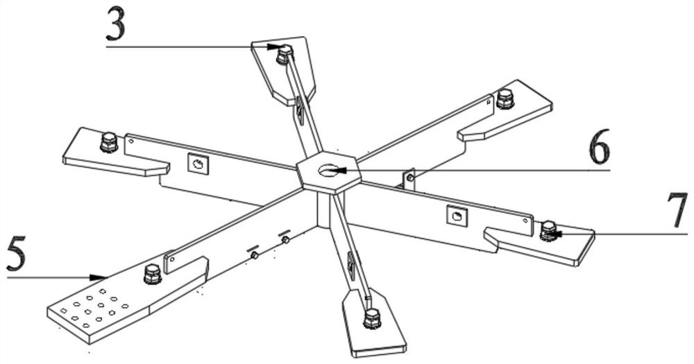
[0032] refer to Figure 1-Figure 3 , an open current-limiting reactor, including a winding and a coil clamping device; the winding includes a plurality of insulating plates 1 and coils, and a plurality of slots 1-1 for accommodating coils are evenly opened on the insulating plate 1; The coil is a bare duralumin flat wire 2, the bare duralumin flat wire 2 is horizontally wound on the slot 1-1 of the insulating plate 1, and the winding is connected with the coil clamping device to clamp and fix the winding. The insulating plate with serrated slot is used for fixing, and the heat dissipation area is increased; the coil is made of bare hard aluminum flat wire, because there is no insulating film wrapped, there is no need to worry about the...


PUM


Abstract

The invention discloses an open type current limiting reactor which comprises a winding and a coil clamping device. The winding comprises a plurality of insulating plates and coils, and a plurality of clamping grooves for accommodating the coils are uniformly formed in the insulating plates; the coil is a bare hard aluminum flat wire, the bare hard aluminum flat wire is horizontally wound on the clamping groove of the insulating plate in the circumferential direction, and the winding is connected with the coil clamping device so as to clamp and fix the winding; the coil clamping device comprises an upper star-shaped frame, a lower star-shaped frame and an insulating pull rod, the upper star-shaped frame is installed at the upper end of the coil, the lower star-shaped frame is installed at the lower end of the coil, the upper star-shaped frame is connected with the lower star-shaped frame through the insulating pull rod, and incoming and outgoing lines of the reactor are led out through the upper star-shaped frame. The bare duralumin flat wire is not wrapped by an insulating film, so that the problem of breakdown of the insulating film in operation of a product does not need to be worried about; and as the product is fixed by adopting the zigzag insulating plate, the heat dissipation area is increased, and the heat dissipation capability of the air-core reactor is enhanced. The invention further discloses a manufacturing method of the open type current limiting reactor.

Description

technical field [0001] The invention relates to the field of power electronic equipment, in particular to an open current-limiting reactor and a manufacturing method thereof. Background technique [0002] The current limiting reactor used in the power grid is essentially an air-core coil without magnetic conductive material, which can be arranged in three assembly forms: vertical, horizontal and zigzag according to needs. When a short circuit occurs in the power system, a large short-circuit current will be generated. If it is not limited, it is very difficult to maintain the dynamic and thermal stability of electrical equipment. Therefore, in order to meet the breaking capacity requirements of some circuit breakers, a current limiting reactor is often connected in series at the outgoing circuit breaker to increase the short-circuit impedance and limit the short-circuit current. [0003] The common current-limiting reactor on the market is a closed current-limiting reactor,...

Claims


Application Information

Patent Timeline
Patent Type & Authority Applications(China)
IPC IPC(8): H01F27/28H01F27/30H01F27/32H01F27/08H01F27/06H01F41/061H01F41/098H01F41/12
CPCH01F27/2876H01F27/306H01F27/2847H01F27/08H01F27/327H01F27/06H01F41/061H01F41/098H01F41/127Y02E40/30
Inventor 辛永会李明王涛陈建秋唐荣徽
Owner SHANDONG HADA ELECTRIC
Why Eureka
Try Eureka