Eureka AIR delivers breakthrough ideas for toughest innovation challenges, trusted by R&D personnel around the world.

Heat preservation coil structure for directional single crystal precision casting furnace

A technology of precision casting and casting furnace, which is applied in the field of thermal insulation coil structure of directional single crystal precision casting furnace, which can solve the problems of single thermal insulation and slow down cooling function of thermal insulation coil, unable to meet product process requirements, etc., and achieve the effect of improving production efficiency

Pending Publication Date: 2022-06-07
SHANGHAI YUANDING TECH CO LTD
View PDF0 Cites 0 Cited by
  • Summary
  • Abstract
  • Description
  • Claims
  • Application Information

AI Technical Summary

Problems solved by technology

[0004] The products of directional single crystal precision casting furnace need to carry out precise temperature control and cooling during the cooling process to ensure that the products complete the crystallization and solidification according to the requirements, but the traditional heat preservation coil only has a single function of heat preservation and slow down cooling (traditional heat preservation coil structure such as Figure 7 shown), so that the overall heat preservation of the product is cooled at the same temperature, which cannot meet the technical requirements of the product for its internal crystal structure, direction, etc.

Method used


Image

  • Heat preservation coil structure for directional single crystal precision casting furnace
  • Heat preservation coil structure for directional single crystal precision casting furnace
  • Heat preservation coil structure for directional single crystal precision casting furnace

Examples


Embodiment Construction

[0027] The technical solutions in the embodiments of the present invention will be clearly and completely described below with reference to the accompanying drawings in the embodiments of the present invention. Obviously, the described embodiments are only a part of the embodiments of the present invention, but not all of the embodiments. Based on the embodiments of the present invention, all other embodiments obtained by those of ordinary skill in the art without creative efforts shall fall within the protection scope of the present invention.

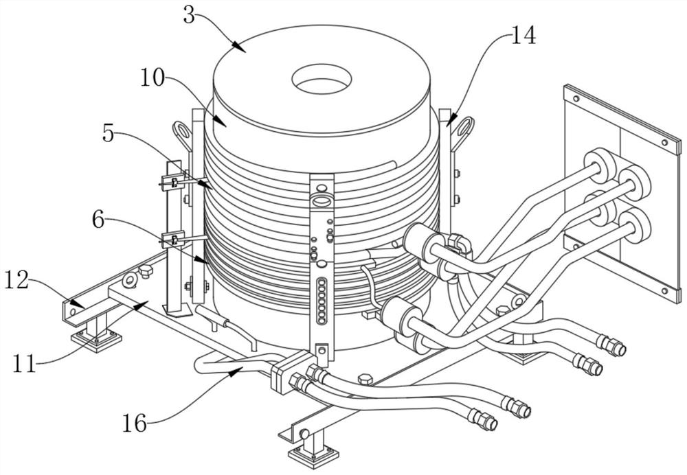
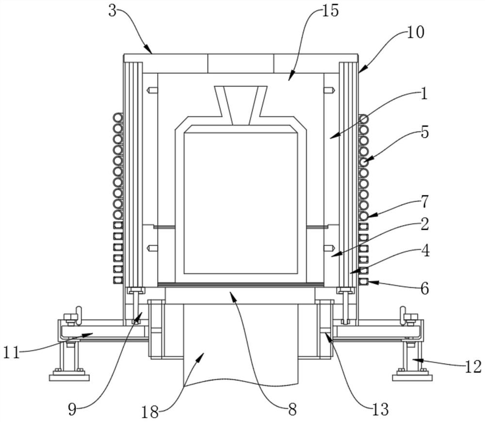
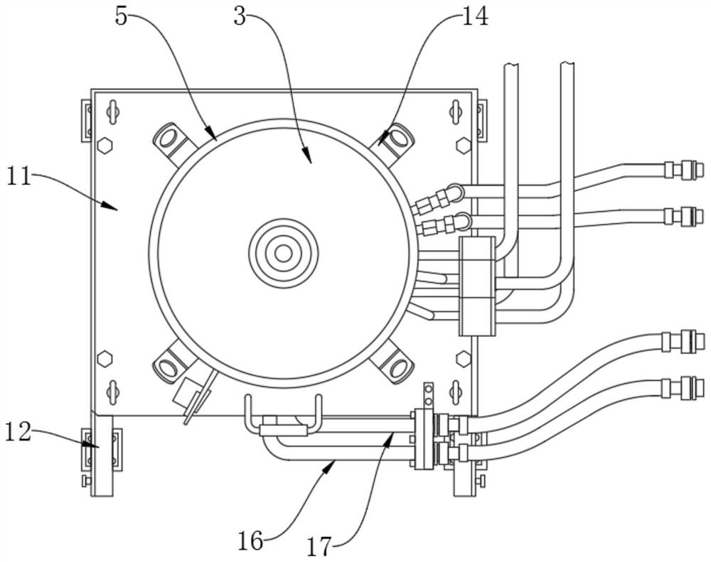
[0028] Refer to the manual attached Figure 1-4 , a heat preservation coil structure for an oriented single crystal precision casting furnace in this embodiment includes a heat preservation coil assembly installed outside the melting chamber 15 of the casting furnace, and the heat preservation coil assembly includes an upper heat preservation coil 5 and a lower heat preservation coil 6 , the upper heat preservation coil 5 and the lowe...


PUM


Abstract

The invention discloses a heat preservation coil structure for a directional single crystal precision casting furnace, and particularly relates to the technical field of casting furnace heat preservation coils, the heat preservation coil structure comprises a heat preservation coil assembly installed on the outer side of a smelting chamber of the casting furnace, and the heat preservation coil assembly comprises an upper heat preservation coil and a lower heat preservation coil; the upper heat preservation coil and the lower heat preservation coil are distributed up and down and arranged on the outer side of the smelting chamber. The heat preservation coil assembly is divided into the upper heat preservation coil and the lower heat preservation coil, and different temperatures can be set at the same time, so that a product in the smelting chamber is located at the upper temperature and the lower temperature, and the crystallization time and the crystallization direction of an internal crystal phase are different according to different temperatures in the product cooling and solidification process. Different temperatures are set for the upper heat preservation coil and the lower heat preservation coil according to the characteristics, so that the crystallization direction of the product is controlled, and the product meeting the process requirement is produced.

Description

technical field [0001] The invention relates to the technical field of heat preservation coils for casting furnaces, and more particularly to a heat preservation coil structure for directional single crystal precision casting furnaces. Background technique [0002] The directional single crystal precision casting furnace uses the principle of electromagnetic induction and current thermal effect to heat and melt the material in the melting chamber into liquid metal. Then pour the liquid metal into the mold shell to maintain a certain temperature requirement in the heat preservation bag, and finally realize the directional solidification and crystallization of the casting through the crystal pulling mechanism. [0003] The directional single crystal precision casting furnace establishes a temperature gradient in a specific direction in the investment casting shell, so that the molten alloy solidifies according to the required crystalline orientation in the opposite direction t...

Claims


Application Information

Patent Timeline
Patent Type & Authority Applications(China)
IPC IPC(8): B22D27/04B22D46/00
CPCB22D27/045B22D46/00Y02P10/25
Inventor 汪澎李心钰
Owner SHANGHAI YUANDING TECH CO LTD
Why Eureka
Eureka Blog
Learn More