
Device and method for measuring yield stress of viscous debris flow

A yield stress and measuring device technology, applied in the fields of geological engineering and debris flow disaster prevention, can solve the problems of inability to measure the yield stress of full-size debris fluid, poor repeatability of measurement results, time-consuming viscous debris flow, etc., and achieve stable calculation results and test results. Small sample, high precision effect

Pending Publication Date: 2022-06-24
NANCHANG HANGKONG UNIVERSITY
View PDF0 Cites 0 Cited by
  • Summary
  • Abstract
  • Description
  • Claims
  • Application Information

AI Technical Summary

Problems solved by technology

Therefore, traditional commercial rheometers cannot measure the yield stress of full-size debris fluids;
[0004] (2) Scholars at home and abroad have developed a variety of rheometers such as large-scale vertebral plate rheometers, large-scale concentric cylinder rheometers, and large-scale plate rheometers to carry out rheological tests. The operation requirements of the rheometer are relatively high, coupled with the influence of factors such as particle settlement and uneven shear during the measurement process, the measurement results of the self-made rheometer are often poor in repeatability and low in accuracy
Therefore, it is very time-consuming to obtain the yield stress of viscous debris flow by using inclined-plane rheometer, and a large number of test debris flow samples of target density are prepared to carry out the yield stress test of debris flow

Method used


Image

  • Device and method for measuring yield stress of viscous debris flow
  • Device and method for measuring yield stress of viscous debris flow
  • Device and method for measuring yield stress of viscous debris flow

Examples


Embodiment 1

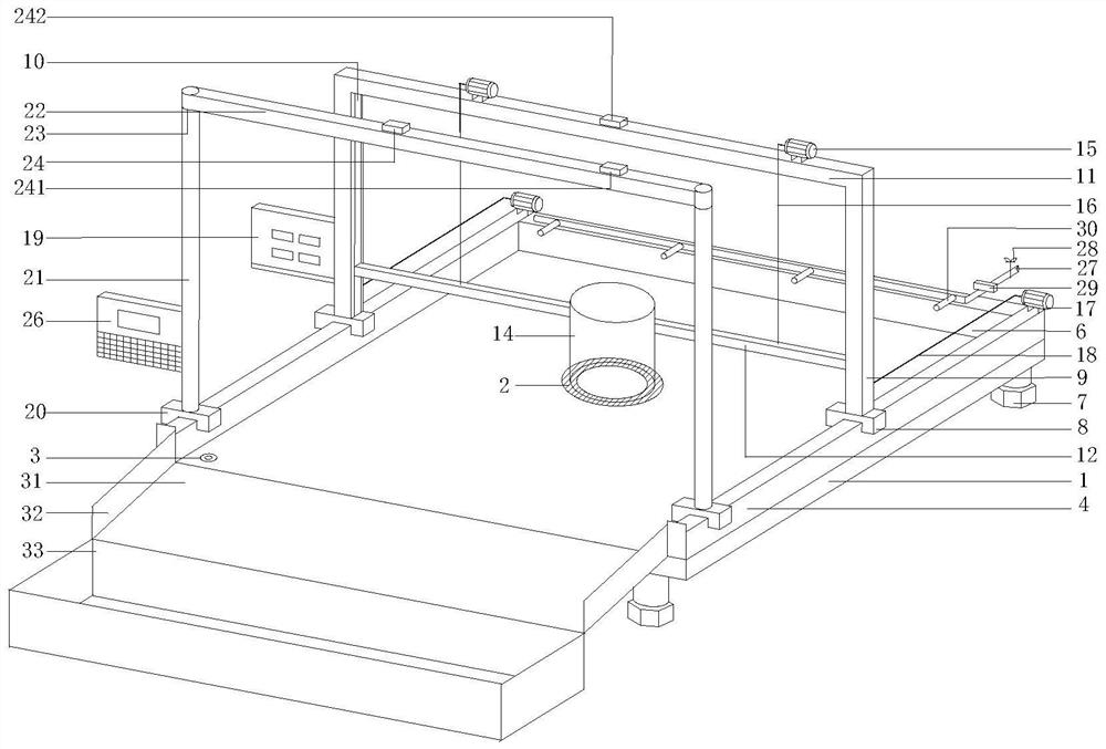
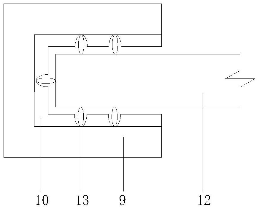
[0062] Example 1: as Figure 1-10 As shown, the viscous debris flow yield stress measurement device includes a yield stress measurement platform, a slump-expansion bucket lifting device, a traction device, a yield stress measurement and analysis device, and a cleaning and recovery device;

[0063] The yield stress measurement platform includes a rectangular flat plate 1, an annular de-energized electromagnet 2, a bubble level 3, a rectangular guide rail 4, a rectangular magnet 5, a transverse baffle 6 and a leveling foot 7; the lower left corner of the rectangular flat plate 1 is provided with a The bubble level 3 can be centered by adjusting the length of the leveling feet 7; the annular de-energized electromagnet 2 is embedded in the center of the rectangular flat plate 1, and is connected to an independent power supply unit of the power supply device 19 through a wire, It has magnetism in the case of power-off, but has no magnetism in the case of power-on; the rectangular g...


PUM


Abstract

The invention discloses a viscous debris flow yield stress measuring device and method. The viscous debris flow yield stress measuring device comprises a yield stress measuring platform, a slump-expansion degree barrel lifting device, a traction device, a yield stress measuring and analyzing device and a cleaning and recycling device. Through the slump-expansion degree barrel lifting device and the traction device, the cylindrical slump-expansion degree barrel filled with the viscous debris flow can be lifted from the yield stress measurement platform to be completely separated from a test sample so as to carry out a slump-expansion degree test. After the collapse-expansion of the debris flow on the yield stress measurement platform is completed, the yield stress measurement and analysis device acquires and processes the data of the debris flow accumulation body on the yield stress measurement platform to obtain the yield stress of the viscous debris flow, and then the yield stress is displayed on the yield stress measurement and analysis device. After the test is finished, the yield stress measuring platform is cleaned up through the cleaning and recycling device, and meanwhile debris flow materials after the test can be recycled through the recycling water tank.

Description

technical field [0001] The invention relates to the technical field of geological engineering and debris flow disaster prevention, in particular to a yield stress measuring device and method for viscous debris flow. Background technique [0002] Debris flow is a common geological disaster caused by precipitation (rainstorm, snowmelt, glaciers) that entrains a large amount of solid materials such as mineral debris, rock debris, and wood chips. Due to its characteristics of sudden outbreak, short duration, ferocious onset and strong destructive power, once a mudslide disaster occurs, it will easily lead to the destruction of the lives and properties of local residents. Yield stress is one of the key rheological parameters of viscous debris flow, which can not only reflect the structural properties and structural strength of viscous debris flow, but also control the mechanical properties and motion law of viscous debris flow. The research on the yield stress measurement method...

Claims


Application Information

Patent Timeline
IPC IPC(8): G01N11/00G01M10/00
CPCG01N11/00G01M10/00
Inventor 杨愧
Owner NANCHANG HANGKONG UNIVERSITY
Learn More