Hydraulic system and method for composite action control of loading machine

A compound action, hydraulic system technology, applied in mechanical equipment, earth movers/shovels, fluid pressure actuating devices, etc. Improve work productivity and operational continuity, with low engine power and strong operational controllability

Active Publication Date: 2022-07-01
XCMG CONSTR MACHINERY
View PDF5 Cites 1 Cited by
  • Summary
  • Abstract
  • Description
  • Claims
  • Application Information

AI Technical Summary

Problems solved by technology

The present invention solves the problem that the boom and the bucket cannot perform combined actions or be controlled more precisely by adopting a simpler, more reliable and more economical method

Method used


Image

  • Hydraulic system and method for composite action control of loading machine
  • Hydraulic system and method for composite action control of loading machine

Examples


Embodiment 1

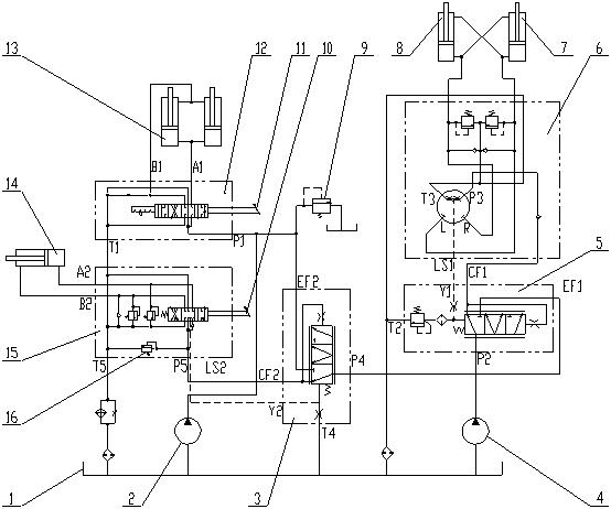
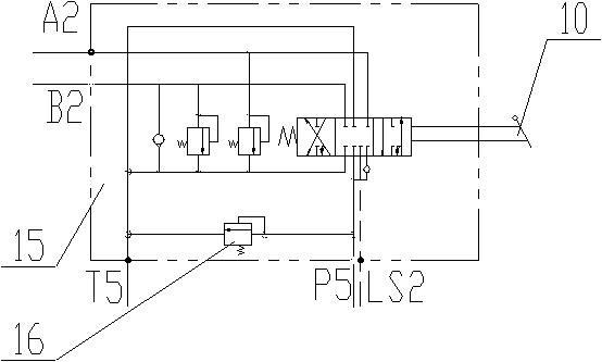
[0040] combine figure 1 and figure 2 As shown, a loader compound action control hydraulic system,

[0041] The oil suction port of the first hydraulic pump 2 is connected to the hydraulic oil tank 1 through a pipeline, and the oil outlet of the first hydraulic pump 2 is connected to the oil inlet P1 of the first control valve 12. The first joystick 11 can control the first control valve. 12 spool action. The A1 port of the first control valve 12 is connected to the rodless cavity of the boom cylinder 13, the B1 port of the first control valve 12 is connected to the rod cavity of the boom cylinder 13, and the T1 port of the first control valve 12 is connected to the hydraulic tank 1 connected.

[0042] The oil suction port of the second hydraulic pump 4 is connected to the hydraulic oil tank 1 through a pipeline, and the oil outlet port of the second hydraulic pump 4 is connected to the oil inlet port P2 of the third control valve 5 . The oil outlet EF1 of the third contro...

Embodiment 2

[0056] On the basis of the above-mentioned first embodiment, a method for controlling a composite action of a loader includes the following steps:

[0057] When steering and boom lift operations are performed at the same time;

[0058] Push the first joystick 11 to control the first control valve 12, so that the spool of the first control valve 12 is moved to the right or left to change direction. At this time, the first hydraulic pump 2 directly supplies oil to the rodless cavity of the boom cylinder 13 Or there is a rod cavity to realize the lifting or lowering of the boom;

[0059] At the same time, the steering wheel controls the rotation and reversal of the internal valve core of the steering gear 6. When the internal valve core of the steering gear 6 rotates, a load signal will be output from the feedback oil port LS1 of the steering gear 6 into the control port Y1 of the third control valve 5 to push the third The spool of the control valve 5 moves to the right, so tha...


PUM


Abstract

The invention discloses a hydraulic system and method for composite action control of a loading machine. The first hydraulic pump sucks oil from the hydraulic oil tank and is connected with the first control valve, and the first control valve is connected with the movable arm oil cylinder; a second hydraulic pump sucks oil from the hydraulic oil tank and is connected with a third control valve, and the third control valve is connected with a steering gear and a fourth control valve; the steering gear is connected with the right steering oil cylinder and the left steering oil cylinder; the fourth control valve is connected with the second control valve and the first control valve. The second control valve is connected with the tipping bucket oil cylinder; the third control valve preferentially supplies oil to the steering gear, and redundant flow is supplied to the fourth control valve; the fourth control valve preferentially supplies oil to the second control valve, and redundant flow is supplied to the first control valve. Composite action of the movable arm oil cylinder and the tipping bucket oil cylinder is achieved, the two molecular systems can be independently controlled, operation controllability is higher, the pressure and the operation speed of the two molecular systems can be independently set, and overlarge impact during unloading is avoided.

Description

technical field [0001] The invention relates to the technical field of construction machinery, in particular to a hydraulic system and method for compound action control of a loader. Background technique [0002] In the process of shovel loading, in order to improve the work efficiency, the loader often uses the compound action of the boom and the tipping bucket to perform efficient work. Completing one action and then performing another action will greatly reduce the work efficiency. Completing the two actions at the same time can greatly save work time. [0003] The control valves currently used in the hydraulic system of the loader are mostly in series structure, and the lifting or lowering control of the boom and the action of tipping or closing the bucket cannot be performed at the same time, which affects the continuity of the loader operation and the operations of shovel loading and unloading. efficiency. [0004] Since the traditional loader dual-pump confluence hy...

Claims


Application Information

Patent Timeline
Patent Type & Authority Applications(China)
IPC IPC(8): F15B11/17F15B11/02F15B13/02F15B13/06F15B13/16E02F9/22
CPCF15B11/17F15B11/02F15B13/02F15B13/06F15B13/16E02F9/2292E02F9/225E02F9/2267F15B2211/20538F15B2211/20546F15B2211/20576
Inventor 郭文明钟俊伟张安民鲍奎宇孟令超赵锦刘浩张爱霞
Owner XCMG CONSTR MACHINERY
Why Eureka
Try Eureka