
Machining method and device for ultra-long and ultra-thin sleeve parts

A processing method and ultra-thin technology, applied in metal processing equipment, manufacturing tools, comprehensive factory control, etc., can solve problems such as difficult to overcome deformation, ensure surface roughness, position accuracy and small roughness

Pending Publication Date: 2022-07-05
CHINA COAL ZHANGJIAKOU COAL MINING MACHINERY
View PDF8 Cites 1 Cited by
  • Summary
  • Abstract
  • Description
  • Claims
  • Application Information

AI Technical Summary

Problems solved by technology

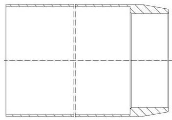
One end of the sleeve part is stepped, the diameter of the outer circle is Φ149.15mm, the wall thickness is 0.525mm, the depth is 366mm, the roughness of the inner and outer circles is 0.8μm, and the roundness is not more than 0.05mm. No more than 0.03mm, so the sleeve is an ultra-long and ultra-thin sleeve part. In the thin-walled inner hole and outer circular surface, there are not only requirements for size and shape accuracy, but also higher position accuracy and smaller roughness. It is difficult to overcome the deformation caused by clamping force, cutting force and cutting heat, etc., and the machining accuracy of shape and position cannot be guaranteed. Since the hole is a step hole, it cannot be bored, ground and other processing methods to ensure the surface. roughness

Method used


Image

  • Machining method and device for ultra-long and ultra-thin sleeve parts
  • Machining method and device for ultra-long and ultra-thin sleeve parts
  • Machining method and device for ultra-long and ultra-thin sleeve parts

Examples


Embodiment Construction

[0015] The present invention will be further described below in conjunction with the accompanying drawings and embodiments.

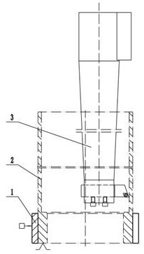
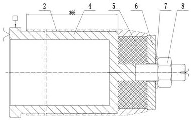
[0016] like figure 1 As shown in the figure, the ultra-long and ultra-thin sleeve parts have not only the size and shape accuracy requirements on the thin-walled inner hole and outer surface, but also higher position accuracy and smaller roughness value requirements. Boring, grinding and other processing methods cannot be used to ensure surface roughness. Therefore, the processing method chooses turning, the final machining of the inner hole is completed on the vertical CNC lathe, and the final machining of the outer circle is completed on the horizontal CNC lathe; The sequence of the outer circle; the inner hole is processed with a slotted sleeve for clamping, and the outer circle is processed with a special device for a thin-walled sleeve that changes the direction of the clamping force.

[0017] Specifically include the following steps:

[0018] a...


PUM


Abstract

The invention relates to the technical field of machining and clamps, in particular to a machining method and device for ultra-long and ultra-thin sleeve parts. According to the technical scheme, a turning machining mode is adopted, inner hole final machining is completed on a vertical numerical control lathe, outer circle final machining is completed on a horizontal numerical control lathe, the machining sequence is that the hole is machined first and then the outer circle is machined, a slotted sleeve is adopted for clamping in inner hole machining, and a thin-wall sleeve special device capable of changing the clamping force direction is adopted for outer circle machining. The machining of the ultra-long and ultra-thin sleeve type part is specifically completed through the three procedures of rough turning of an outer circle, turning of an inner hole and finish turning of the outer circle. The special device for the thin-wall sleeve is composed of an installation mandrel, a positioning sleeve, a pressing plate, a gasket and a pressing nut, and the clamping force direction is changed from the radial direction to the axial direction. The special device for the slotted sleeve and the thin-wall sleeve is adopted, so that the requirements for the size, the shape, the position precision and the surface roughness of the inner hole and the outer circle of the ultra-long and ultra-thin sleeve part are met. The method has the beneficial effects that the process method is simple and can be completed in one processing mode, and the production efficiency and the processing quality are high.

Description

technical field [0001] The invention relates to the technical field of machining and fixtures, and relates to a process method for ensuring the manufacturing quality and production efficiency of thin-walled sleeve parts, in particular to a processing method and device for ultra-long and ultra-thin sleeve parts. Background technique [0002] There is a sleeve type part, such as figure 1 As shown in the figure, the casing is installed for the hood of an aircraft. The material is stainless steel, and its manufacturing accuracy plays a key role in product assembly. One end of the sleeve part is stepped, the outer diameter is Φ149.15mm, the wall thickness is 0.525mm, the depth is 366mm, the inner and outer circle roughness is 0.8μm, the roundness is not more than 0.05mm, and the inner and outer circles are concentric with the inner hole of the step. It is not more than 0.03mm, so the sleeve belongs to an ultra-long and ultra-thin sleeve type part. The thin-walled inner hole and ...

Claims


Application Information

Patent Timeline
IPC IPC(8): B23B1/00B23B5/26
CPCB23B1/00B23B5/26Y02P90/02
Inventor 刘彪徐唯辰刘海江石欣欣张江祁峰刘煜
Owner CHINA COAL ZHANGJIAKOU COAL MINING MACHINERY
Learn More