Signal sending method, signal sending device and information interaction system

A technology of a sending method and a sending device, which is applied in the fields of information interaction systems, sending devices, signal sending methods, and automatic control systems, and can solve problems such as large equipment changes, increased uncertainty risks, and risks of credibility, and achieves The effect of reducing development and operation and maintenance costs, reducing the risk of uncertainty, and avoiding the risk of credibility

Pending Publication Date: 2022-07-05
上海芯超半导体科技有限公司
View PDF0 Cites 0 Cited by
  • Summary
  • Abstract
  • Description
  • Claims
  • Application Information

AI Technical Summary

Problems solved by technology

[0007] (1) The lowest-level equipment in the factory cannot use the SECS/GEM protocol to communicate with EAP, so that the upper-level MES cannot obtain the equipment provided by EAP
In order to communicate the above equipment with EAP, it is necessary to contact the equipment manufacturer in the factory to upgrade and transform the equipment. However, the equipment transformation is not only expensive, but also takes a long time to change the equipment. The large changes to the equipment will affect the production capacity. Influence, affect the promotion of automation processes in the factory
[0008] (2) Due to the large number of PLC equipment communication protocols, for example, Siemens' PLC equipment has 3964R protocol, MPI protocol, PPI protocol, and free communication port protocol, Omron's PLC equipment has Host Link protocol, ControlLink protocol, Schneider's PLC equipment has MODBUSTCP protocol, etc. , which makes it difficult to unify the communication protocol layer, resulting in large development and operation and maintenance costs for equip

Method used


Image

  • Signal sending method, signal sending device and information interaction system
  • Signal sending method, signal sending device and information interaction system
  • Signal sending method, signal sending device and information interaction system

Examples


Embodiment Construction

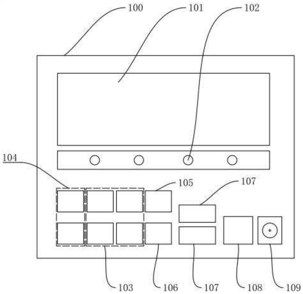
[0064] In order to make the purpose, technical solutions and advantages of the present invention clearer, the following describes the signal sending method, sending device and information interaction system proposed by the present invention in further detail with reference to the accompanying drawings and specific embodiments. The advantages and features of the present invention will become more apparent from the following description. It should be noted that the accompanying drawings are in a very simplified form and all use inaccurate scales, and are only used to facilitate and clearly assist the purpose of explaining the embodiments of the present invention. For the purpose, features and advantages of the present invention to be more clearly understood, please refer to the accompanying drawings. It should be noted that the structures, proportions, sizes, etc. shown in the drawings in this specification are only used to cooperate with the contents disclosed in the specificat...


PUM


Abstract

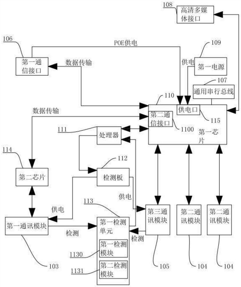
The invention relates to a signal sending method, a signal sending device and an information interaction system. The signal sending device comprises a first power supply, a first chip, a processor, a detection board, a first detection unit, at least one first communication module, at least one second communication module and at least one first communication interface. Through the arrangement of the first chip and the processor, the processor can distribute the power supply after the power supply is transmitted to the power supply port of the first chip, thereby realizing the power supply or non-power supply to the first communication module and the third communication module. According to the transmitting device, the damage condition caused by too high voltage or current after sensors with different voltages or currents are connected with the transmitting device is avoided, the voltage or current matched with the sensor in model, voltage or current can be selectively provided for the sensor, and the power supply state can be detected in real time after power supply through the detection plate; if abnormal data is generated, the abnormal data can be uploaded to the EAP and the MES, and if normal data is generated, normal data can be uploaded to the EAP and the MES.

Description

technical field [0001] The invention relates to the field of information exchange in semiconductor manufacturing, in particular to a signal transmission method, a transmission device and an information exchange system, which are mainly used for converting equipment that does not support SECS / GEM protocol into a unified protocol for transmission to an automatic control system. Background technique [0002] With the development of semiconductor processes, semiconductor manufacturers need to compete fiercely in the volatile global market. Manufacturers must be able to maximize the use of equipment, optimize manufacturing processes and process parameters, increase throughput, and reduce entry. Preparing time for mass production and providing a more flexible and convenient working environment make production more efficient. Due to the increased cost and complexity of the manufacturing process, equipment automation has become a necessary part of front-end semiconductor manufacturi...

Claims


Application Information

Patent Timeline
IPC IPC(8): H04L69/08H04L12/10H04L41/0803H04L67/12G06F13/40G06F13/42G01R31/00G01R19/165G01D21/02
CPCH04L69/08H04L12/10H04L41/0803H04L67/12G06F13/42G06F13/40G01R31/00G01R19/16538G01R19/16571G01R19/16576G01D21/02Y02P90/02
Inventor 不公告发明人
Owner 上海芯超半导体科技有限公司
Why Eureka
Try Eureka