
Lifting device and lifting method for steam turbine rotor

A steam turbine rotor and lifting device technology, which is applied in safety devices, transportation and packaging, load hanging components, etc., can solve the problems of large manpower and material resources for dismantling pipelines, increase safety hazards, increase hoisting workload, etc., and reduce components The effect of lifting risk, reducing lifting activities, and saving lifting costs

Pending Publication Date:
View PDF0 Cites 0 Cited by
  • Summary
  • Abstract
  • Description
  • Claims
  • Application Information

AI Technical Summary

Problems solved by technology

Since the steam inlet and exhaust pipes of this type of steam turbine are located on the top of the cylinder, it will consume a lot of manpower and material resources to remove the pipes, and the workload of hoisting will increase, which will increase safety hazards

Method used


Image

  • Lifting device and lifting method for steam turbine rotor
  • Lifting device and lifting method for steam turbine rotor
  • Lifting device and lifting method for steam turbine rotor

Examples


Embodiment Construction

[0040] A steam turbine rotor hoisting device and hoisting method provided by the present invention will be further described in detail below with reference to the accompanying drawings and specific embodiments.

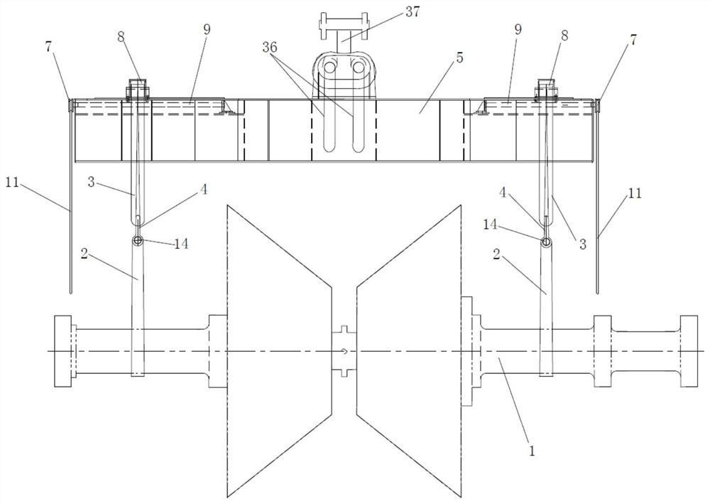
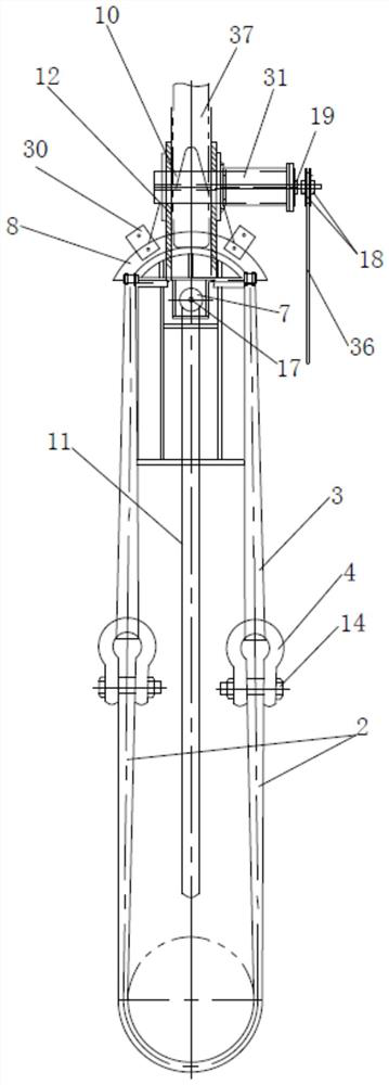
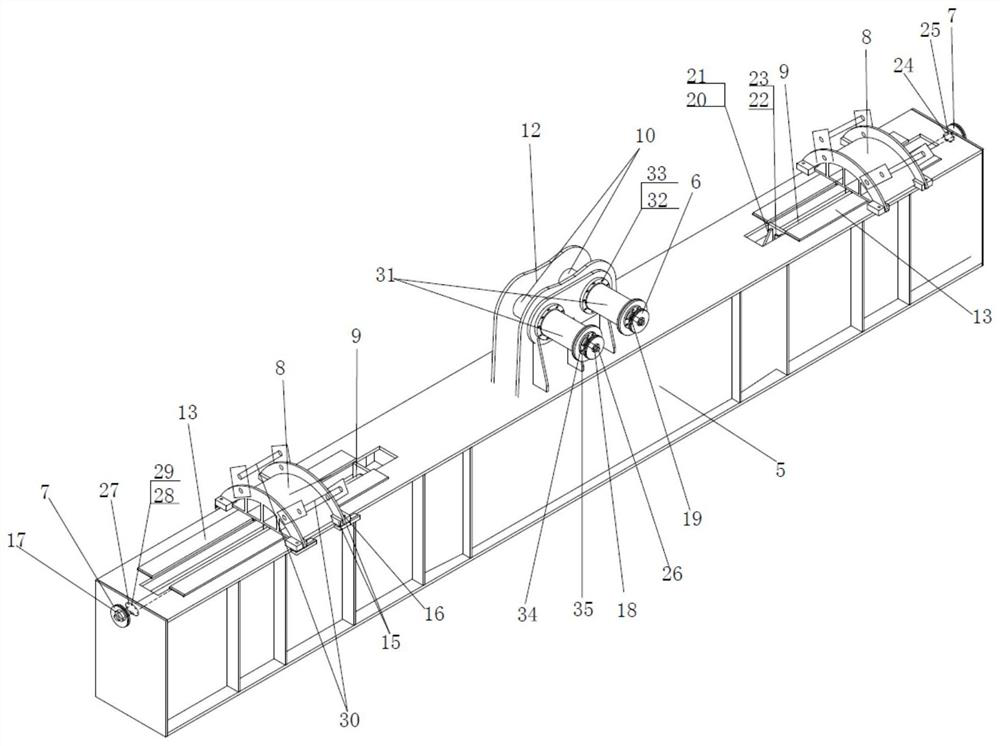
[0041] like Figure 1-3 As shown, the present invention provides a steam turbine rotor hoisting device, including a steam turbine rotor sling 2, a suspending beam sling 3, a shackle 4, a hoisting suspending beam 5, a pulley A6, a pulley B7, a saddle 8, a guide rod 9, a pin shaft 10. Hand zipper 11, hanging beam lifting lug 12, slide rail 13, shackle bolt 14, locking limit block 15, locking bolt A16, locking bolt B17, locking bolt C18, locking bolt D19, fixing Plate 20, fixing bolt 21, locking plate A 22, locking bolt E 23, locking plate B 24, locking bolt F 25, screw 26, limit plate A 27, locking bolt F 28, locking washer 29. Sling limit rod 30, sleeve 31, fastening bolt A 32, fastening gasket 33, limit plate B 34, fastening bolt B 35, hand zipper B36, driving hook 3...


PUM


Abstract

The invention belongs to the technical field of mechanical equipment maintenance, and particularly relates to a steam turbine rotor lifting device and a lifting method. According to the invention, the whole body of the lifting beam lifting point penetrates through the lifting beam main body, is welded with the middle position of the lifting beam main body, and is a lifting point of the lifting device; the hanging beam hanging belts are hung on the hanging beam body through the sliding saddles and distributed on the two sides of the hanging beam body in a central symmetry mode, and the sliding saddles can slide on the hanging beam body. The steam turbine rotor hanging belt is connected with the hanging beam hanging belt; the steam turbine rotor hanging belt is sleeved on a steam turbine rotor; the sleeve is fastened on the lifting beam lifting lug, the pin shaft is installed in the sleeve, a thread is arranged in the center of the pin shaft, the pin shaft is connected with the screw rod in a matched mode and used for connecting the lifting beam lifting lug with a crane lifting hook, and the pulley A is fastened on the screw rod and integrated with the screw rod. And the crane lifting hook, the lifting beam and the lifting point form a lifting device bearing point. The lifting device is simple in structure, easy to operate, convenient to maintain, high in universality and capable of being used for lifting any similar rotor parts within the rated load of the lifting beam.

Description

technical field [0001] The invention belongs to the technical field of mechanical equipment maintenance, and particularly relates to a steam turbine rotor hoisting device and a hoisting method. Background technique [0002] A steam turbine, also known as a steam turbine engine, is a rotary steam power device. The high-temperature and high-pressure steam passes through a fixed nozzle to become an accelerated airflow and then sprays it onto the blades, causing the rotor with the blades to rotate while doing external work. Steam turbines are widely used and are the main equipment for modern thermal power stations, nuclear power stations, biomass power generation and so on. [0003] A certain type of steam turbine, single-shaft four-cylinder six-exhaust steam reheating condensing type, output 1,127,000kW (before capacity increase) [0004] / 1176000kW (after capacity increase), speed 1500 rpm, frequency 50Hz, equipped with three low-pressure rotors and one high-pressure rotor wi...

Claims


Application Information

Patent Timeline
Patent Type & Authority Applications(China)
IPC IPC(8): B66C1/18B66C15/00B66C13/00
CPCB66C1/18B66C15/00B66C13/00Y02E30/00
Inventor 柴广许准陈亮薛彦春赵勇余浩别国泰曹亮亮王仁昌王建忠吕志彦
Learn More