
Residue soil improvement system of shield tunneling machine

A technology of muck improvement and shield machine, which is applied in the direction of earth square drilling, mining equipment, tunnels, etc. It can solve the problems of poor fluidity of dregs, unfavorable discharge of muck, and blockage of soil bins by mud, and achieve good flow plasticity and small Effects of friction resistance and low water permeability

Inactive Publication Date: 2022-07-08
江苏西尔德建设工程有限公司
View PDF0 Cites 0 Cited by
  • Summary
  • Abstract
  • Description
  • Claims
  • Application Information

AI Technical Summary

Problems solved by technology

[0002] In shield tunneling construction, especially in complex strata and special stratums, when excavating in water-bearing strata, muck with high water content will easily form a soil plug effect in the screw conveyor, causing gushing; in sticky soil stratum During excavation, the fluidity of the dregs is poor, and the dregs are highly abrasive to the cutter and the screw conveyor, which is not conducive to the discharge of the muck, which will cause the mud to block the soil bin or the screw conveyor, resulting in the inability of the shield machine to continue. Operation

Method used


Image

  • Residue soil improvement system of shield tunneling machine
  • Residue soil improvement system of shield tunneling machine
  • Residue soil improvement system of shield tunneling machine

Examples


Embodiment 1

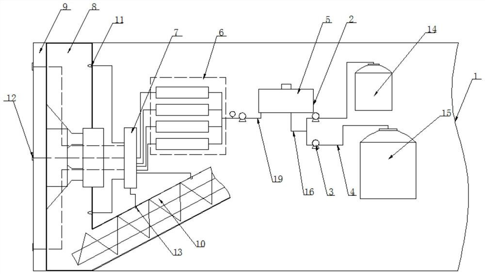
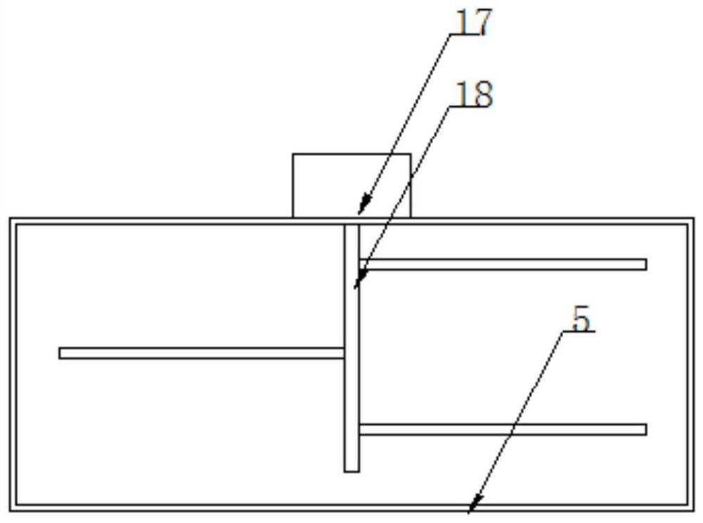
[0028] like Figure 1-2 As shown, a shield machine muck soil improvement system includes a shield machine body 1, and the front end of the shield machine body 1 is provided with a cutter head 9, a soil bin 8 and a screw conveyor 10, and the soil bin 8 is located in the cutter head 9. The rear side is connected with the discharge flow channel on the cutter head 9. The screw conveyor 10 is fixedly installed at the bottom of the rear side of the soil bin 8 and communicated with the bottom of the soil bin 8. There is also a foam system 2 for injecting foaming agent into the muck to improve it, wherein the foam system 2 includes:

[0029] The raw material supply assembly, including the foaming agent storage tank 14 and the solvent water storage tank 15, is used to supply the foam processing raw materials to the front end of the foam system 2, and the two are respectively connected to the inlet end of the infusion header 16 through an infusion branch pipe 4, and two A quantitative ...

Embodiment 2

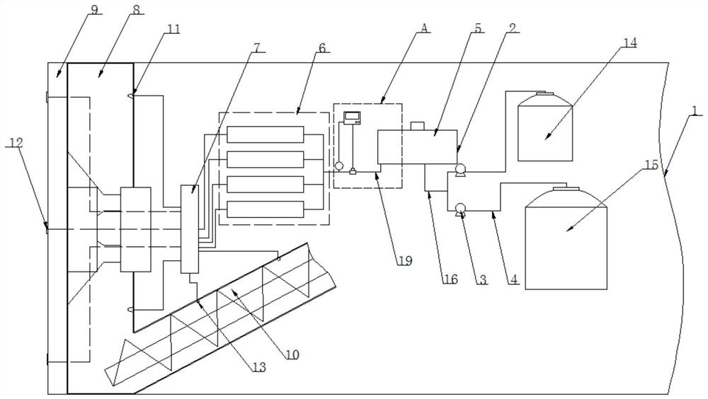
[0041] In order that the foam system 2 can quantitatively spray the foaming agent according to the actual amount of the excavated slag, as well as the slag soil quality and water content of the excavation surface, so as to achieve the best improvement effect of the slag, this embodiment is described in Example 1. 1 to make further improvements, such as Figure 3-4 As shown, a quantitative controller 22 is also fixedly installed in the shield machine body 1, which is respectively connected with the flow sensor 21 and the infusion pump 20 to receive and accumulate the flow value of the flow sensor 21, and when the accumulated value reaches the required value When the set quantitative control value is set, the infusion pump 20 is controlled to work.

[0042] The total injection volume of the foaming agent of the foam injection component of the cutter head, the foam injection component of the soil bin, and the foam injection component of the conveyor is 300-600L per cubic slag.

...


PUM


Abstract

The invention discloses a shield tunneling machine muck improvement system, and belongs to the technical field of shield tunneling machine muck improvement, the shield tunneling machine muck improvement system comprises a shield tunneling machine body, the front end of the shield tunneling machine body is provided with a cutterhead, a soil bin and a screw conveyor, the soil bin is located on the rear side of the cutterhead and is communicated with a discharging runner on the cutterhead, and the screw conveyor is fixedly installed at the bottom of the rear side of the soil bin; the shield tunneling machine comprises a shield tunneling machine body, the shield tunneling machine body is internally provided with a soil bin, the soil bin is communicated with the bottom of the soil bin, and the shield tunneling machine body is further internally provided with a foam system used for injecting a foaming agent into muck so as to improve the muck. The additive is mixed with the soil slag through rotary stirring of the cutter head, stirring of the soil bin stirring device or rotary stirring of the spiral conveyor, so that the slag soil cut by a shield has good flow plasticity, appropriate consistency, low water permeability and small frictional resistance, and the ideal working condition of shield tunneling under different geological conditions can be met.

Description

technical field [0001] The invention belongs to the technical field of shield machine slag soil improvement, and particularly relates to a shield machine slag soil improvement system. Background technique [0002] In shield construction, especially in complex strata and special stratum shield construction, when the water-bearing stratum is excavated, the slag with a large water content is likely to form a soil plug effect in the screw conveyor, causing gushing; in the cohesive soil stratum During excavation, the fluidity of the ballast soil is poor, and the muck is more abrasive to the cutter and the screw conveyor, and it is not conducive to the discharge of the ballast soil, which in turn causes the soil to block the soil bin or the screw conveyor, resulting in the shield machine being unable to continue. Operation. [0003] Therefore, we need to inject foam into the surface of the cutter disk, the soil bin or the screw conveyor, so that the ballast soil cut by the shield...

Claims


Application Information

Patent Timeline
Patent Type & Authority Applications(China)
IPC IPC(8): E21D9/06E21D9/087E21D9/12
CPCE21D9/0678E21D9/0685E21D9/087E21D9/124
Inventor 纪承鹏张球生
Owner 江苏西尔德建设工程有限公司
Learn More