
Wireless power transmission system

A technology of wireless energy transmission and wireless energy, which is applied in the field of wireless energy transmission system and wireless charging, can solve the problems of slow communication speed, signal interference, large loss, etc., and achieve the effect of low cost and fast communication rate

Pending Publication Date: 2022-07-08
深圳市磁迹科技有限公司
View PDF0 Cites 0 Cited by
  • Summary
  • Abstract
  • Description
  • Claims
  • Application Information

AI Technical Summary

Problems solved by technology

[0003] For long-distance wireless power transmission technology, there are currently two commonly used communication technologies: one is in-band communication. The impact of power transmission will also become greater and greater, which will have a greater impact on the signal quality of the power supply. In addition, the communication speed is relatively slow, which cannot meet the requirements in many occasions; the other is Bluetooth or 2.4G communication mode, the communication speed is relatively fast, but Due to the wide variety of Bluetooth transmission protocols and other 2.4G devices, and they all share signals in this frequency band, it will inevitably lead to mutual interference between signals in this frequency band; secondly, the Bluetooth wireless communication protocol is not a free technology, any manufacturer using Bluetooth technology must pay a patent fee to Bluetooth-related organizations, and this part of the fee is usually reflected in the cost of the product, resulting in an increase in cost
[0004] The existing wireless power transmission system includes a power receiving device coil module that receives power and a charging coil module that transmits power; when charging, if the positions of the power receiving coil module and the charging coil module are different, the power transmission efficiency will be reduced, resulting in greater loss , and the above two commonly used communication technologies can only provide relevant communication, but cannot achieve distance detection and angle detection, so additional devices and equipment need to be added to realize this function

Method used


Image

  • Wireless power transmission system
  • Wireless power transmission system
  • Wireless power transmission system

Examples


Embodiment 1

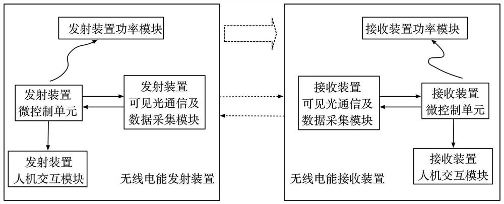
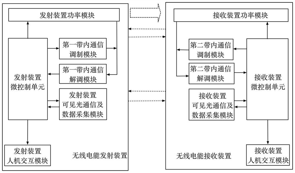
[0030] like figure 1 As shown, the wireless power transmission system includes a wireless power transmitting device and a wireless power receiving device, and the wireless power transmitting device includes a transmitting device micro-control unit, a transmitting device power module controlled by the transmitting device micro-control unit, and a transmitting device visible light communication and data acquisition module. The wireless power receiving device includes a receiving device micro-control unit, a receiving device micro-control unit that controls the receiving device power module, and a receiving device visible light communication and data acquisition module; the transmitting device micro-control unit and the receiving device power module through wireless transmission of power, The visible light communication and data acquisition module of the transmitting device and the visible light communication and data acquisition module of the receiving device communicate with eac...

Embodiment 2

[0038] On the basis of Embodiment 1, the visible light communication and data acquisition module of the transmitting device further includes a first incident angle analysis circuit and a first signal processing circuit; the first photoelectric detection module detects the angle of the visible light emitted by the wireless power receiving device, through The first incident angle analysis circuit analyzes the incident angle and azimuth of the light, and transmits the relevant angle signal to the micro-control unit of the transmitting device through the first signal processing circuit. The visible light communication and data acquisition module of the receiving device also includes a second incident angle analysis circuit and a second signal processing circuit; the second photoelectric detection module detects the angle of the visible light emitted by the wireless energy transmitting device, and analyzes the light through the second incident angle circuit. The incident angle and a...

Embodiment 3

[0043] like Image 6 As shown, the two-dimensional plane xoy is taken as an example to illustrate that the first photoelectric detection module and the second photoelectric detection module implement distance analysis and angle analysis.

[0044] The first photoelectric detection module or the second photoelectric detection module detects the point with the strongest illumination, that is, the visible light irradiates the point perpendicular to the arc surface of the first photoelectric detection module or the second photoelectric detection module and receives the maximum light intensity. The angle analysis circuit and the first signal processing circuit or the second incident angle analysis circuit and the second signal processing circuit analyze the angle α between the incident direction of the visible light and the horizontal x-axis, according to the intensity of the light, through the first small signal amplifier circuit and The first filter circuit obtains the amplitude s...


PUM


Abstract

The invention discloses a wireless power transmission system. The wireless electric energy transmission system comprises a wireless electric energy transmitting device and a wireless electric energy receiving device. The wireless electric energy transmitting device comprises a transmitting device micro-control unit, a transmitting device power module controlled by the transmitting device micro-control unit, and a transmitting device visible light communication and data acquisition module. According to the wireless electric energy transmission system, visible light is adopted for real-time communication, distance detection and angle detection between the wireless electric energy transmitting device and the wireless electric energy receiving device, electromagnetic interference cannot be generated due to the characteristics of the visible light, other devices cannot be affected by electromagnetic waves, and related crosstalk does not exist between the devices; therefore, the extremely high communication rate is achieved, and the highest communication rate can reach more than 10 Gpbs.

Description

technical field [0001] The present invention relates to the technical field of power electronics, in particular to wireless charging technology, and more particularly, to a wireless power transmission system realized by visible light real-time communication. Background technique [0002] With the rise of wireless power transmission in recent years, the function of wireless power transmission has become more and more popular in consumer electronics and industrial fields, and wireless power transmission has gradually approached our daily life. The wireless power transmission products in the prior art can be divided into two types according to the distance: one is the short-range wireless power transmission technology, the transmission distance is within 10mm, such as the wireless power transmission of the mobile phone close-up; the other is the long-distance wireless power transmission technology. Wireless power transmission technology, the transmission distance is more than 1...

Claims


Application Information

Patent Timeline
Patent Type & Authority Applications(China)
IPC IPC(8): H02J50/90H02J50/12H02J7/02
CPCH02J50/90H02J50/12H02J7/02
Inventor 潘星星李刚明陈宇李光平
Owner 深圳市磁迹科技有限公司
Learn More