
Bio-ink supply system and three-dimensional bio-printing method using same

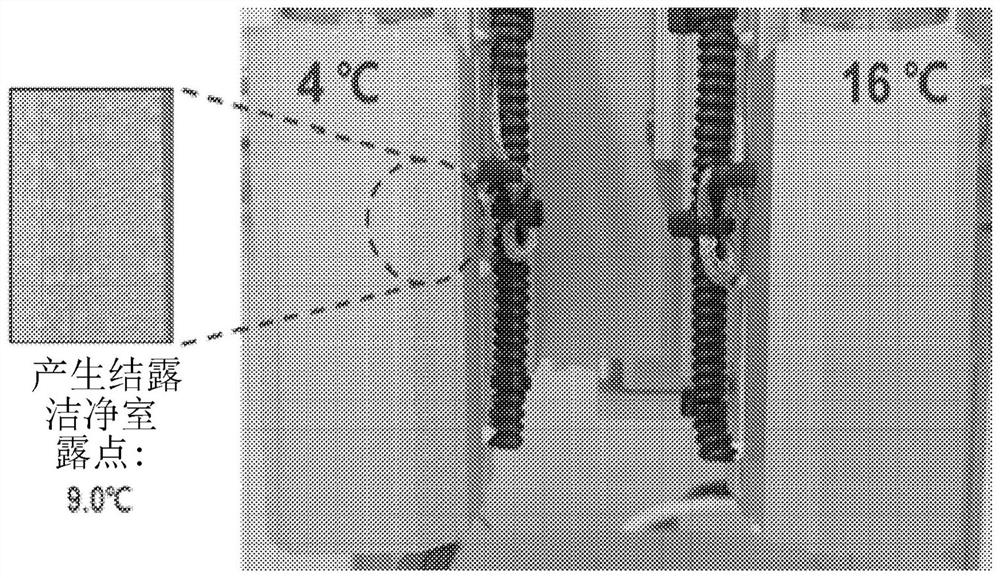
A bio-ink and supply system technology, applied in 3D printers, 3D printing systems, 3D bioprinting, and 3D printing fields, can solve problems such as high cost, physical or biological pollution of printed results, and achieve the effect of reducing power consumption

Pending Publication Date: 2022-07-08
T&R BIOFAB
View PDF4 Cites 0 Cited by
  • Summary
  • Abstract
  • Description
  • Claims
  • Application Information

AI Technical Summary

Problems solved by technology

Generally speaking, a clean 3D bioprinting environment can be created by arranging a 3D bioprinter in a clean room, but this has the problems of high cost and the need for special certified equipment
In addition, even if clean air is supplied through the clean room, stagnant areas are generated due to the flow of air (air flow), and pollution sources such as particles gather in such stagnant areas, thereby causing the problem of physical or biological contamination of printed products

Method used


Image

  • Bio-ink supply system and three-dimensional bio-printing method using same
  • Bio-ink supply system and three-dimensional bio-printing method using same
  • Bio-ink supply system and three-dimensional bio-printing method using same

Examples


Embodiment

[0121]After the heating block was formed on the outer peripheral surface of the syringe from which the printing composition was discharged, a cap was formed with a thickness of 3 mm so that the heating block was wrapped with polyetherether ketone, thereby constituting a high temperature head for a 3D printer.

experiment example 1

[0124] [Experimental Example 1: Measurement of Thermal Insulation Properties]

[0125] In order to measure the thermal insulation performance of the 3D printing head of the present invention, the temperature of the heating block of the example and the comparative example was set to 100°C, and then the surface temperature of the cover of the example and the heating block of the comparative example were measured within 1 hour. surface temperature, the results are shown in Image 6 .

[0126] from the above Image 6 From the results of , in the case of the comparative example, the temperature increased from 23.8°C in the initial stage to 103.9°C in 10 minutes, and then the temperature was kept constant. In contrast, in the case of the example, the temperature rose from the initial stage 24.7°C to 81.9°C in 10 minutes, and then the temperature remained constant, so it was confirmed that the example including the cover had a thermal insulation effect of about 20°C.

[0127] Fi...

experiment example 2

[0195] Experimental Example 2: Measurement of the printed result according to the water level of the bio-ink

[0196] Three-dimensional bioprinting was carried out by setting the same conditions as air pressure and moving speed of the syringe, and only changing the water level of the bioink in the syringe to measure the amount of bioink discharged from the syringe. The results are shown in Table 1.

[0197] [Table 1]

[0198] Water level of bio-ink (ml) Discharge (ml) 2.0 0.069±0.004 0.5 0.080±0.001

[0199] As confirmed by the results in Table 1, it can be seen that when the water level of the bioink in the syringe was 0.5 ml, the discharge amount increased by about 17% compared to when the water level of the bioink was 2.0 ml. This means that the amount of bioink expelled through the syringe during bioprinting varies according to the level of bioink in the syringe. Therefore, it can be seen that for precise bioprinting, the water level of the bi...


PUM

PropertyMeasurementUnit
thicknessaaaaaaaaaa

Abstract

The present invention relates to a bio-ink supply system, and more particularly, to a bio-ink supply system comprising: a hydrogel storage part; a cell storage unit; a mixing unit for receiving the hydrogel and the cell solution from the hydrogel storage unit and the cell storage unit; a sensor part for measuring the water level of the bio-ink inside the syringe; and a control section that receives a signal from the sensor section to maintain a constant water level of the bio-ink inside the syringe, and the mixing section supplies the bio-ink prepared by mixing a hydrogel and a cell solution to the syringe. The bio-ink supply system according to the present invention can continuously supply active bio-ink to a syringe of a bio-printer even in a 3D bio-printing process, and thus can continuously print large-scale living body tissues, or a plurality of orgonoids, organ chips, and the like.

Description

technical field [0001] The present invention relates to a bio-ink supply system, and more particularly, to a bio-ink supply system and a three-dimensional bio-printing method using the same, which can mix hydrogels and cells in real-time and continuously supply bio-ink during a three-dimensional bio-printing process. [0002] Furthermore, the present invention relates to a 3D printing head, and more particularly, to a 3D printing head that does not cause condensation on the low temperature part by improving the thermal insulation performance of the high temperature part, and a 3D printer including the same. [0003] Furthermore, the present invention relates to a biological clean workbench system, and more particularly, to a 3D printing system capable of 3D printing in a biologically stable environment and a 3D printing method using the same. [0004] This work was supported by the Industrial Technology Innovation Program (No. 20000325) funded by the Ministry of Trade, Industr...

Claims


Application Information

Patent Timeline
Patent Type & Authority Applications(China)
IPC IPC(8): B29C64/209
CPCB33Y30/00B29C64/209B33Y70/00B33Y40/10B33Y10/00B29C64/336B29C64/106B29C64/393B33Y40/00B33Y50/02C12M33/00B29C64/255B29C64/314B29C64/321C12M25/14C12N11/04
Inventor 安根先金旼经闵庆贤李仁奎石东原
Owner T&R BIOFAB
Learn More