
Argon blowing protection ladle cover for metal smelting

A technology for metal smelting and protective cover, applied in the field of argon blowing in metal smelting, can solve the problems of working environment and health impact, poor video resolution of running monitoring equipment, high input cost, etc., and achieve the effect of saving volume

Pending Publication Date: 2022-07-15
GANSU JIU STEEL GRP HONGXING IRON & STEEL CO LTD
View PDF0 Cites 0 Cited by
  • Summary
  • Abstract
  • Description
  • Claims
  • Application Information

AI Technical Summary

Problems solved by technology

[0002] During the metal smelting process, the molten high-temperature metal needs to be placed in the ladle. A large amount of dust-containing flue gas generated by the ladle escapes into the working space and pollutes the surrounding environment. There are dust removal facilities installed outside the ladle or a fully sealed dust removal design. In order to effectively control the pollution of smoke and dust to the environment, but the investment cost of the overall dust removal design of the steel ladle is relatively large, and the dust removal facilities need to be opened when inspecting and maintaining the steel ladle and handling accidents, which is extremely inconvenient for personnel to approach and handle. High-definition cameras can be used to solve the problem, but a large amount of smoke and dust accumulated in the sealed space cannot be discharged in time, the video definition of the running monitoring equipment is poor, and the maintenance cost of the monitoring equipment is increased
[0003] A large amount of dust and high temperature have a great impact on the service life of the accessories of the ladle, such as slide plates, hydraulic implements, rubber pipes, transmission bearings, etc., the maintenance cost will also increase, and the maintenance time will increase, which will affect the working environment of the on-site maintenance and maintenance staff have a certain impact on health

Method used


Image

  • Argon blowing protection ladle cover for metal smelting
  • Argon blowing protection ladle cover for metal smelting
  • Argon blowing protection ladle cover for metal smelting

Examples


Embodiment Construction

[0030] The present invention will be further described below with reference to the accompanying drawings and specific embodiments.

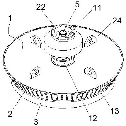
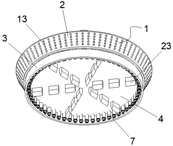
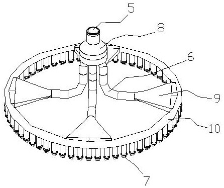
[0031] like Figure 1-6 As shown, a metal smelting argon blowing protective cover, the cover includes a cover body 1, an argon gas conveying mechanism and a dust removal mechanism. The included angle is 15-80°, the lower layer is the retainer 3, and the retainer 3 is provided with a thermal protection cover 4; the argon gas delivery mechanism sequentially includes an argon gas delivery port 5, a connecting pipe 6, an argon blowing chamber and a nozzle 7, and an argon gas delivery mechanism. The delivery port 5 is arranged above the cover body 1, the connecting pipe 6 includes multiple groups, the inlet end of the connecting pipe 6 is connected to the argon gas delivery port 5 through the branch cavity 8, and the argon blowing cavity is arranged in the cover body 1, including fan-shaped blowing. The argon chamber 9 and the annular argon blowing c...


PUM


Abstract

The upper layer of a cover body of the ladle cover is a dust removal wall, the lower layer of the cover body of the ladle cover is a protective ring, and a heat preservation protective cover is arranged in the protective ring; the argon conveying mechanism sequentially comprises an argon conveying opening, connecting pipes, argon blowing cavities and nozzles, the argon conveying opening is formed in the upper portion of the cover body, the gas inlet ends of the multiple sets of connecting pipes are connected with the argon conveying opening through branch cavities, the argon blowing cavities are formed in the cover body and comprise fan-shaped argon blowing cavities and annular argon blowing cavities, the gas supply ends of the connecting pipes are communicated with small openings of the fan-shaped argon blowing cavities, and the annular argon blowing cavities are communicated with small openings of the annular argon blowing cavities. A large opening of the fan-shaped argon-blowing cavity is communicated with the side wall of the annular argon-blowing cavity; a plurality of nozzles are arranged at the bottom of the annular argon-blowing cavity; the bottom end of the dedusting connecting pipe of the dedusting mechanism penetrates into the cover body, the main dedusting opening is communicated with the interior of the cover body through the dedusting connecting pipe, and a plurality of dedusting holes are formed in the dedusting wall. The heat preservation protection cover protects the interior of the ladle cover, a negative pressure cavity is formed in the ladle cover through the main dust removal opening and the external dust suction device, and gas and smoke dust generated by the steel ladle are sucked into the dust removal holes when meeting the dust removal wall and are treated for dust removal.

Description

technical field [0001] The invention belongs to the technical field of argon blowing in metal smelting, and particularly relates to a metal smelting argon blowing protective cover. Background technique [0002] During the metal smelting process, the molten high-temperature metal needs to be placed in the ladle, and a large amount of dust-containing flue gas generated by the ladle escapes into the working space, polluting the surrounding environment. There are dust removal facilities outside the ladle or a fully sealed dust removal design The pollution of smoke and dust to the environment can be effectively controlled, but the investment in the overall dust removal design of the ladle is relatively large, and the dust removal facilities need to be opened when inspecting and maintaining the ladle and handling accidents. It is extremely inconvenient for personnel to approach the treatment. High-definition cameras are used to solve the problem, but a large amount of smoke and du...

Claims


Application Information

Patent Timeline
Patent Type & Authority Applications(China)
IPC IPC(8): B22D1/00B22D41/00B22D45/00
CPCB22D1/005B22D41/00B22D45/005
Inventor 王海
Owner GANSU JIU STEEL GRP HONGXING IRON & STEEL CO LTD
Learn More