Device for automatically cutting wind power flange sample by numerical control lathe and cutting method

A wind power flange and CNC lathe technology, applied in the direction of sampling device, feeding device, positioning device, etc., can solve the problems of insufficient cutting accuracy, difficulty in moving, high failure rate, etc., to ensure safe and stable operation, improve cutting accuracy, and reduce failures rate effect

Active Publication Date: 2022-07-15
SHANXI TIANBAO GRP CO LTD
View PDF5 Cites 2 Cited by
  • Summary
  • Abstract
  • Description
  • Claims
  • Application Information

AI Technical Summary

Problems solved by technology

[0005] The purpose of the present invention is to solve the problems in the prior art that the wind power flange is bulky and difficult to move, the routing of the cutting knife is not easy to control, the cutting precision is not enough, and the cutting mechanism Overheating is prone to occur, the failure rate is high, and the cut debris cannot be cleaned in time. A device and cutting method for automatically cutting wind power flange samples by a CNC lathe are proposed to facilitate the movement of wind power flanges and improve wind power. The accuracy of flange sample cutting reduces the failure rate of cutting devices

Method used


Image

  • Device for automatically cutting wind power flange sample by numerical control lathe and cutting method
  • Device for automatically cutting wind power flange sample by numerical control lathe and cutting method
  • Device for automatically cutting wind power flange sample by numerical control lathe and cutting method

Examples


Embodiment 1

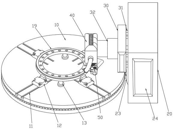
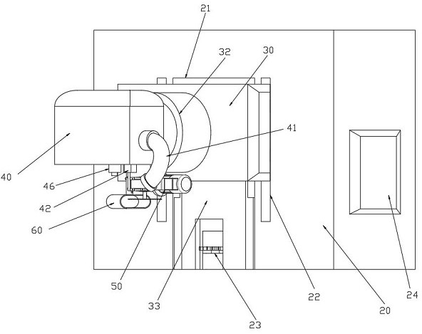
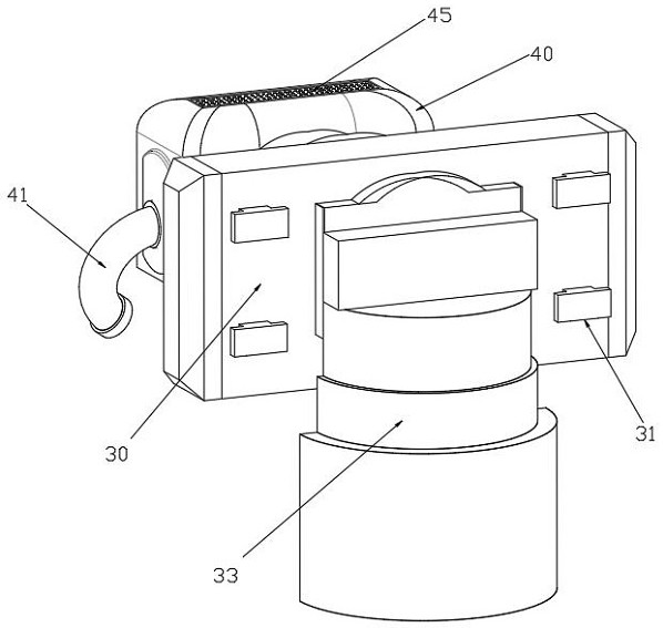
[0035] refer to Figure 1-4 , a device for automatically cutting wind power flange samples by a numerical control lathe, including a bearing turntable 10 and a lathe frame 20, the bearing turntable 10 is a rotatable mechanism, the upper end of the bearing turntable 10 carries a wind power flange 19, A lathe frame 20 is arranged on the side; a vertical hydraulic lift 33 is embedded at one end of the lathe frame 20, and a turntable motor 23 is arranged at the lower part of the lathe frame 20; The lower end of the vertical hydraulic lifter 33 is provided with a turntable gear 15, which meshes with the turntable motor 23; the output end of the vertical hydraulic lift 33 is provided with a bearing bracket 30, and one side of the bearing bracket 30 is connected to the lathe frame 20. In sliding connection, a horizontal hydraulic lift 32 is fixedly arranged on the other side of the support bracket 30 ; an equipment box 40 is fixedly arranged at the output end of the horizontal hydrau...

Embodiment 2

[0043] This embodiment is a cutting method of a device for automatically cutting a wind power flange sample using a numerically controlled lathe involved in the first embodiment, and the method for cutting a wind power flange sample includes the following steps:

[0044] Step S1: First, according to the diameter of the wind power flange 19, preset the position where the wind power flange 19 is placed on the bearing turntable 10, and according to the position, place the support column 13 evenly along the circumference at the lower part where the wind power flange 19 is to be placed , the wind power flange 19 is hoisted to a preset position by a crane, so that the support column 13 is carried in the middle of the circumference of the wind power flange 19;

[0045] Step S2: After the wind power flange 19 is stably placed in the preset position, the fixing bolts 18 are inserted into the turntable chute 11, the mounting holes of the limit assembly 12 are sleeved on the fixing bolts ...


PUM


Abstract

The invention discloses a device for automatically cutting a wind power flange sample by a numerically controlled lathe and a cutting method. The device comprises a bearing turntable and a lathe frame, a wind power flange is borne at the upper end of the bearing turntable, and a vertical hydraulic elevator is embedded in one end of the lathe frame; a bearing frame is arranged at the output end of the vertical hydraulic elevator, one side of the bearing frame is slidably connected with the lathe frame, a horizontal hydraulic elevator is fixedly arranged on the other side of the bearing frame, an equipment box is fixedly arranged at the output end of the horizontal hydraulic elevator, a semiconductor refrigerator is arranged in the equipment box, and an air guide pipe is arranged on one side of the equipment box. A cutting mechanism is arranged on one side of the lower end of the equipment box, and a cutting knife is installed at the output end of the cutting mechanism and abuts against the wind power flange. The problem that the wind power flange is heavy and difficult to move is solved, the cutting stroke of the wind power flange and the temperature of the cutting mechanism can be monitored in real time, safe and stable operation of the cutting mechanism is ensured, and the failure rate is reduced.

Description

technical field [0001] The invention relates to the technical field of cutting wind power flange samples, in particular to a device and a cutting method for automatically cutting wind power flange samples by a numerically controlled lathe. Background technique [0002] Wind power flange is an important load-bearing component for connecting wind power equipment. It is necessary to strictly control the macroscopic deformation and microstructure state of the ring during the forming process. The mechanical properties of the flange provide a scientific reference. It is necessary to cut the produced wind power flange samples to verify whether the mechanical properties of the wind power flange meet the requirements of use. [0003] At present, for the cutting of large wind power flange samples on the market, there is no special sample cutting device, and cutting tools are used to directly cut wind power flanges. There are the following problems that need to be solved urgently: It ...

Claims


Application Information

Patent Timeline
Patent Type & Authority Applications(China)
IPC IPC(8): B23Q3/00B23Q1/25B23Q5/34B23Q11/10B23Q11/00B23Q17/24B23Q17/09G01N1/04
CPCB23Q3/00B23Q1/25B23Q5/34B23Q11/10B23Q11/0042B23Q17/2409B23Q17/0985G01N1/04B23Q2703/10
Inventor 胡大为闫志龙樊璟赟王历亮李晋候树伟于大海谭振杰郭焕平张雁玲郝军伟郭振华赵文军
Owner SHANXI TIANBAO GRP CO LTD
Why Eureka
Try Eureka