High-temperature decomposition device and method for industrial tail gas containing N2O

A technology for pyrolysis and industrial tail gas, applied in the direction of separation methods, combustion methods, chemical instruments and methods, etc., can solve the problems of reducing denitrification agent, catalyst use efficiency, increasing the processing burden of catalytic decomposition system, reactor and catalyst damage, etc. , to reduce the amount of denitrification treatment, prevent excessive temperature fluctuations, and improve the service life

Pending Publication Date: 2022-07-15
河南神马减碳技术有限责任公司
View PDF0 Cites 0 Cited by
  • Summary
  • Abstract
  • Description
  • Claims
  • Application Information

AI Technical Summary

Problems solved by technology

Among them, in N 2 The catalytic decomposition reaction of O is a highly exothermic reaction. In order to control the reaction temperature, a large amount of air must be blown into the air compressor to dilute the raw material gas, which not only greatly increases the processing burden of the catalytic decomposition system, but also reduces the use efficiency of denitration agents and catalysts. In addition, if the reaction temperature is not well controlled, it is easy to cause damage to the reactor and catalyst due to high temperature, which is not conducive to cost reduction and efficiency increase

Method used


Image

  • High-temperature decomposition device and method for industrial tail gas containing N2O
  • High-temperature decomposition device and method for industrial tail gas containing N2O
  • High-temperature decomposition device and method for industrial tail gas containing N2O

Examples


specific Embodiment

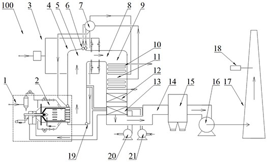
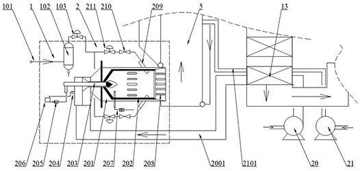
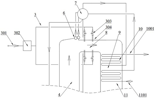
[0054] Specific examples are as follows, such as figure 1 shown: one for N 2 O high-temperature decomposition device of industrial tail gas, including raw gas intake system 1, high-temperature decomposition furnace 2, kiln 4, denitration agent distribution system 3, and denitration catalyst packing layer 12;

[0055] The feed gas intake system 1 includes a feed gas source 101 and a gas-liquid separator 102 communicating with the feed gas source. A feed gas control valve 103 is provided at the gas outlet end of the gas-liquid separator 102, and the feed gas control valve can control the entry of feed gas into The speed and air intake of the pyrolysis furnace; the gas-liquid separator can remove the nitrogen-containing 2 O Nitric acid or mist droplets in industrial tail gas, realize the purification and drying of raw material gas;

[0056] Among them, the inlet end of the pyrolysis furnace 2 is communicated with the raw material gas intake system 1, and the dried raw material ...


PUM


Abstract

The invention provides a high-temperature decomposition device and method for industrial tail gas containing N2O. The high-temperature decomposition device comprises a raw material gas inlet system, a high-temperature decomposition furnace, a kiln, a denitration agent distribution system and a denitration catalyst packing layer, the gas inlet end of the high-temperature decomposition furnace is communicated with a raw material gas inlet system and is used for high-temperature decomposition of raw material gas; the kiln comprises a vertically arranged hearth and a heat recovery flue, and the hearth is communicated with the heat recovery flue through a denitration flue; the hearth is communicated with a combustion chamber of the high-temperature decomposition furnace; the denitration agent distribution system comprises a plurality of groups of denitration agent spray guns which are uniformly distributed in the circumferential direction of the denitration flue; the denitration catalyst packing layer is arranged at the outlet end of the heat recovery flue and used for catalytic decomposition of denitration flue gas. According to the high-temperature decomposition device, air dilution does not need to be conducted on raw material gas, accurate control over the reaction temperature is achieved, the industrial tail gas denitration treatment capacity is greatly reduced, and the use efficiency of a denitration agent and a denitration catalyst is improved; the reaction temperature is controllable, and the service life of the kiln and the denitration catalyst is prolonged.

Description

technical field [0001] The invention relates to the technical field of industrial tail gas treatment, in particular to a 2 O high-temperature decomposition device and method of industrial exhaust gas. Background technique [0002] Industrial exhaust usually contains a large amount of nitrogen oxides. Nitrogen oxides usually include nitrous oxide, nitrogen monoxide, nitrogen dioxide, nitrous oxide, nitrous oxide, etc. The direct discharge of industrial exhaust gas containing nitrogen oxides will burden on the atmosphere. [0003] For containing N 2 For the treatment of industrial exhaust gas of O, the conventional treatment method is to decompose nitrogen oxides by catalytic decomposition. In the process of catalytic decomposition, N 2 O converts to N 2 , O 2 and a small amount of NO, NO 2 , a small amount of NO and NO 2 Then through the SCR reactor for catalytic reduction reaction to generate H 2 O and N 2 O, so as to realize the harmless treatment of industrial exh...

Claims


Application Information

Patent Timeline
Patent Type & Authority Applications(China)
IPC IPC(8): F23G5/46F23G5/50F23G7/06B01D53/56B01D53/75
CPCF23G5/46F23G7/065F23G5/50B01D53/56B01D53/75B01D53/346
Inventor 张电子赵铎张昌会刘镇江田言峰钟儒学李增光李晓叶姚鑫宋铭铭冯欣赵晓伟刘雯张思维苏钰涵
Owner 河南神马减碳技术有限责任公司
Why Eureka
Try Eureka