Fuel nozzle, combustion chamber and gas turbine engine

A technology of fuel nozzle and fuel oil, which is applied in the field of combustion chamber, gas turbine engine and fuel nozzle, which can solve the problems of convective heat transfer of purge gas which is difficult to limit heat, reduce the heating effect of oil circuit, etc., so as to reduce the risk of fuel coking, Eliminates the effects of direct impact and avoids fuel coking

Active Publication Date: 2022-07-19
AECC COMML AIRCRAFT ENGINE CO LTD
View PDF9 Cites 0 Cited by
  • Summary
  • Abstract
  • Description
  • Claims
  • Application Information

AI Technical Summary

Problems solved by technology

[0010] However, in the prior art scheme, the front end of the nozzle shell is in direct contact with the front end of the oil collector ring and the fuel nozzle, and the main function of the heat insulation chamber in the prior art is to reduce the heating effect on the oil circuit after the nozzle shell is subjected to radiation heat exchange, so it is difficult to limit the heat. The convective heat transfer caused by the purge gas

Method used


Image

  • Fuel nozzle, combustion chamber and gas turbine engine
  • Fuel nozzle, combustion chamber and gas turbine engine
  • Fuel nozzle, combustion chamber and gas turbine engine

Examples


no. 1 example

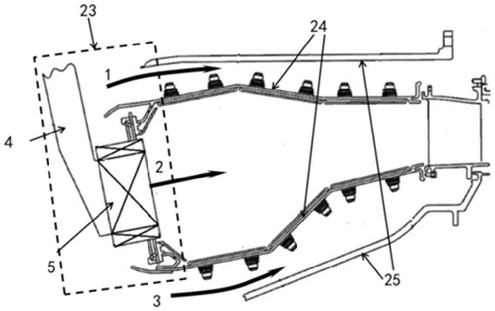
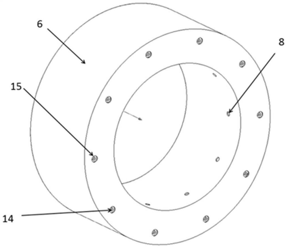
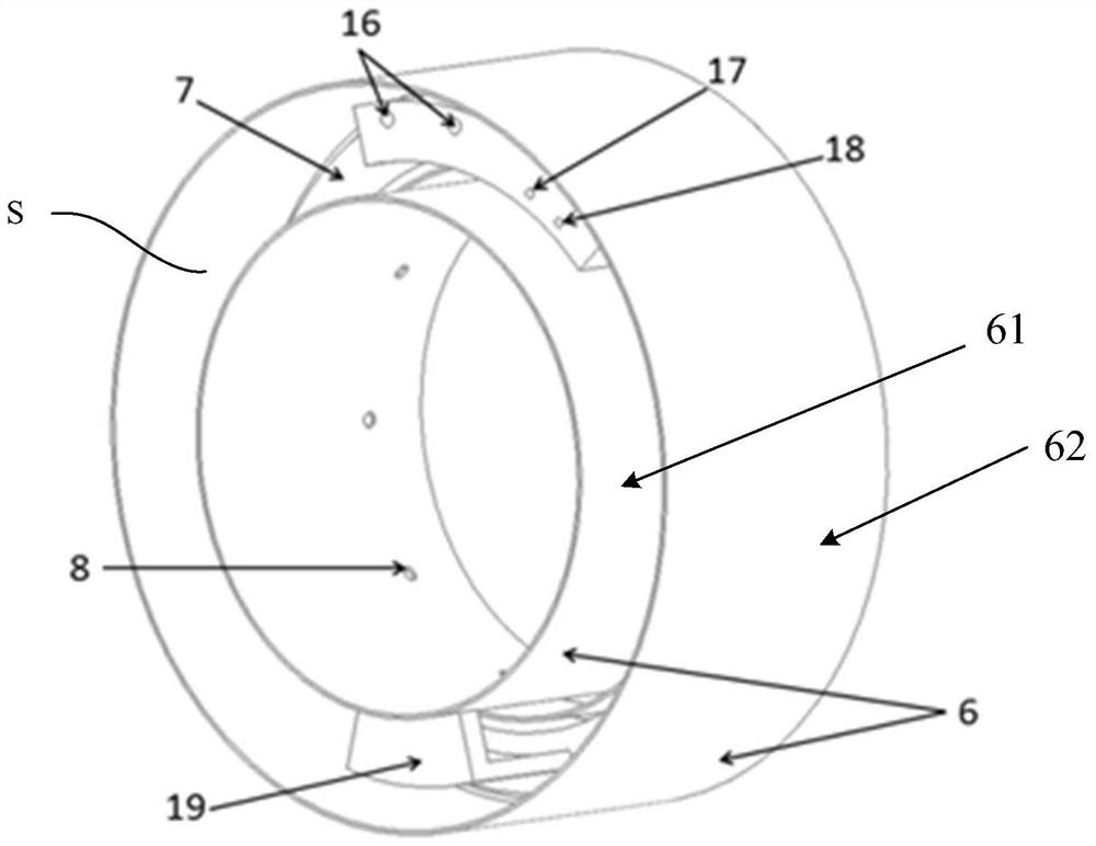
[0047] like Figure 2 to Figure 6 As shown, the fuel nozzle 23 includes a rod core 4 , an oil collecting ring 5 and a nozzle housing 6 , and the nozzle housing 6 provides an accommodating space S for accommodating the oil collecting ring 5 in the accommodating space S. The specific structure of the nozzle housing 6 may include a radial inner wall 61 and a radial outer wall 62, the radial gap between the radial inner wall 61 and the radial outer wall 62 defines the accommodation space S, and the radial inner wall 61 has a circumferential distribution. The air hole 8 is formed, so that the hot air flow enters the accommodating space from the air hole 8, so as to realize the differential pressure purging of the residual fuel when the fuel nozzle stops running.

[0048] The oil collecting ring 5 has an oil collecting ring body 7 and an oil passage 100 located inside the oil collecting ring body 7, for example Figure 4A as well as Figure 4B The shown can include the main oil ci...

no. 2 example

[0052] The parts of the second embodiment that are the same as those of the first embodiment will not be described in detail here.

[0053] refer to Figure 7A , Figure 7B as well as Figure 8 As shown, the heat insulation cavity of the second embodiment is a semi-closed heat insulation cavity 13 with one end closed and one end open. , demand and other factors to change the shape and protection area of ​​the thermal insulation cavity), and avoid the position where the fuel nozzle 14 protrudes. The difference between the semi-closed thermal insulation cavity 13 and the thermal insulation cavity 12 is that the air in the semi-closed thermal insulation cavity 13 communicates with the outside of the thermal insulation cavity. The air flow in the cavity 13 is slow, and the thermal protection effect equivalent to that of the closed thermal insulation cavity 12 can be achieved.


PUM


Abstract

The invention relates to a fuel nozzle, a combustion chamber and a gas turbine engine. Wherein the fuel nozzle comprises a rod core; the oil collecting ring is provided with an oil collecting ring body, an oil way located in the oil collecting ring body and a fuel oil nozzle protruding out of the oil collecting ring body, one end of the oil way is fixedly connected with the rod core, and the other end of the oil way is connected with the fuel oil nozzle; and a nozzle housing defining an accommodation space; wherein the oil collecting ring is contained in the containing space, and the oil collecting ring body and the fuel nozzle are not in contact with the nozzle shell.

Description

technical field [0001] The invention belongs to the technical field of gas turbine engines, and in particular relates to a fuel nozzle, a combustion chamber and a gas turbine engine. Background technique [0002] The fuel nozzle of aero-engine is mainly affected by the convection heat transfer from the outlet air of the high-pressure compressor and the radiation heat transfer of the gas in the flame tube in the combustion chamber. As the inlet temperature of the combustion chamber increases, the wall temperature of the oil passage in the fuel nozzle and the temperature of the fuel oil also increase continuously. The higher temperature of the fuel wet wall causes the fuel to react with the dissolved oxygen in it, and deposit and coke on the oil wall surface, which reduces the flow area of ​​the fuel pipeline, and even blocks the nozzle in severe cases, affecting the fuel atomization effect. The worsening fuel atomization effect will lead to the deterioration of the combustio...

Claims


Application Information

Patent Timeline
Patent Type & Authority Applications(China)
IPC IPC(8): F23R3/28F23R3/42
CPCF23R3/28F23R3/42
Inventor 冯健黄望全田晨陈浩
Owner AECC COMML AIRCRAFT ENGINE CO LTD
Why Eureka
Try Eureka