Optical fiber vibration sensor with temperature self-compensation function

An optical fiber vibration and sensor technology, applied in vibration testing, instrument, machine/structural component testing, etc., can solve the problems of limited sensor measurement frequency band, complex vibration measurement system, temperature cross-sensitivity, etc. Simple, ultra-small effect

Pending Publication Date: 2022-07-22
XI AN JIAOTONG UNIV +1
View PDF0 Cites 0 Cited by
  • Summary
  • Abstract
  • Description
  • Claims
  • Application Information

AI Technical Summary

Problems solved by technology

Due to the influence of the resonant frequency and mechanical stability of the cantilever beam itself, the measurement frequency band of this type of sensor is limited, and there are problems of temperature cross-sensitivity; in addition, the existing optical fiber vibration sensors usually require complex demodulation of phase, wavelength, light intensity, etc. The device is used to complete the extraction of the sensor signal, which leads to the complexity and high cost of the whole vibration measurement system

Method used


Image

  • Optical fiber vibration sensor with temperature self-compensation function
  • Optical fiber vibration sensor with temperature self-compensation function
  • Optical fiber vibration sensor with temperature self-compensation function

Examples


Embodiment Construction

[0034] The present invention will be further described below in conjunction with the embodiments and the accompanying drawings.

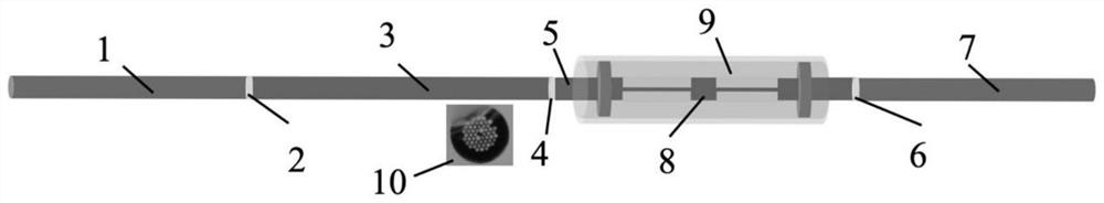
[0035] like figure 1 As shown, an optical fiber vibration sensor with temperature self-compensation function includes a first single-polarization fiber 1, and the output end of the first single-polarization fiber 1 is connected by a first fusion point 2 and the input end of the first high birefringence photonic crystal fiber 3 , the output end of the first high birefringence photonic crystal fiber 3 is connected to the input end of the second high birefringence photonic crystal fiber 5 through the second fusion point 4, and the output end of the second high birefringence photonic crystal fiber 5 is connected by the third fusion point 6 and The input end of the second single-polarization optical fiber 7 is connected, and the middle of the second high birefringence photonic crystal fiber 5 prepares an optical fiber in-line micro cantilever beam 10 wit...


PUM


Abstract

An optical fiber vibration sensor with a temperature self-compensation function comprises a first single-polarization optical fiber, and the output end of the first single-polarization optical fiber is connected with the input end of a first high-birefringence photonic crystal optical fiber through a first welding point. The output end of the first high-birefringence photonic crystal fiber is connected with the input end of a second high-birefringence photonic crystal fiber through a second welding point, and the output end of the second high-birefringence photonic crystal fiber is connected with the input end of a second single-polarization fiber through a third welding point. An optical fiber on-line micro cantilever beam with a micro hanging weight is prepared in the middle of the second high-birefringence photonic crystal fiber, and a rigid capillary tube is arranged outside the optical fiber on-line micro cantilever beam; the optical axis of the single-polarization optical fiber and the optical axis of the high-birefringence photonic crystal optical fiber form an angle of 45 degrees, and the optical axes of the two high-birefringence photonic crystal optical fibers are orthogonal; according to the invention, the flat frequency response characteristic is provided for vibration signals with the frequency in the frequency band range of 5Hz-5kHz, and the antenna has the advantages of simple structure, low manufacturing cost and easy industrialization.

Description

technical field [0001] The invention relates to the technical field of optical fiber vibration sensors, in particular to an optical fiber vibration sensor with temperature self-compensation function. Background technique [0002] Vibration sensor is a detection device that captures environmental vibration information, and is widely used in various fields such as production and life, equipment status monitoring, and intelligent manufacturing. The existing electrical vibration sensor has poor anti-electromagnetic interference capability, narrow measurement frequency band, low sensitivity, requires power supply, and cannot meet the vibration measurement requirements in harsh environments such as substations in harsh electromagnetic environments, underground coal mines rich in gas, and oil wells. Compared with traditional electrical sensors, optical fiber vibration sensors have the advantages of strong electromagnetic interference resistance, high sensitivity and passive nature....

Claims


Application Information

Patent Timeline
IPC IPC(8): G01H9/00G01M7/02
CPCG01H9/004G01M7/025
Inventor 韩春阳丁晖金祎顾渊博
Owner XI AN JIAOTONG UNIV
Why Eureka
Try Eureka