Check patentability & draft patents in minutes with Patsnap Eureka AI!

Resistance measuring circuit, resistance measuring method and digital multimeter

A resistance measurement and circuit technology, applied in the measurement of resistance/reactance/impedance, measurement of electrical variables, multi-tester circuits, etc., can solve problems such as large resistance errors, and achieve the effect of improving measurement accuracy and reducing factors of measurement accuracy.

Pending Publication Date: 2022-07-22
SHENZHEN CITY SIGLENT TECH
View PDF0 Cites 0 Cited by
  • Summary
  • Abstract
  • Description
  • Claims
  • Application Information

AI Technical Summary

Problems solved by technology

At present, the principle of digital multimeter to measure resistance is based on Ohm's law. Generally, multimeters use the voltage division method to measure resistance. The error between the measured value and the true value is large

Method used


Image

  • Resistance measuring circuit, resistance measuring method and digital multimeter
  • Resistance measuring circuit, resistance measuring method and digital multimeter
  • Resistance measuring circuit, resistance measuring method and digital multimeter

Examples


Embodiment 1

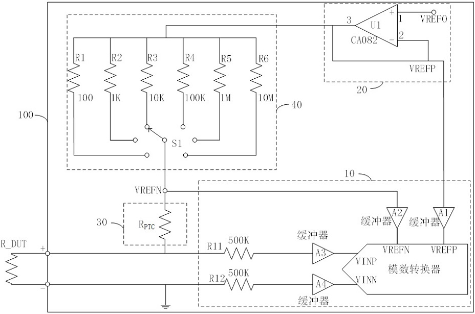
[0048] Please refer to figure 2 , is a schematic diagram of the circuit connection of the resistance measurement circuit in another embodiment. The resistance measurement circuit 100 is used to measure the resistance value of the resistance R_DUT to be measured. The resistance measurement circuit 100 includes a measurement positive connection terminal, a measurement negative connection terminal, a constant voltage power supply circuit 20 , a resistance bank circuit 40 , a current protection circuit 30 and an analog-to-digital conversion circuit 10 . The measurement positive connection terminal and the measurement negative connection terminal are used to connect with both ends of the resistance R_DUT to be measured, respectively. The current protection circuit 30 is respectively connected to the measurement positive connection terminal and the resistance bank circuit 40. The current protection circuit 30 is used to provide overcurrent protection to the resistance measurement c...

Embodiment 2

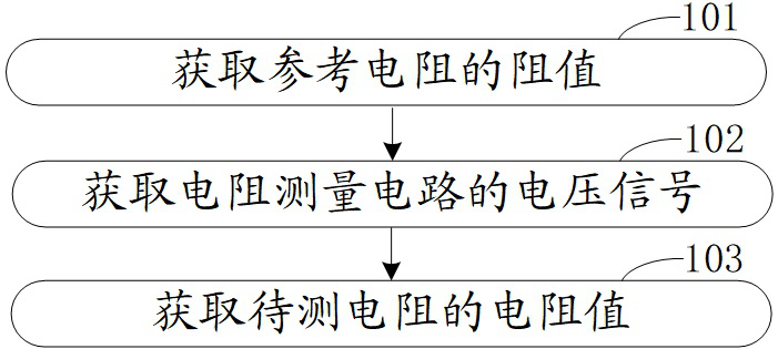
[0078] Please refer to image 3 , is a schematic flow chart of the resistance measurement method in another embodiment, the resistance measurement method is applied to the resistance measurement circuit as described in the first embodiment, and the resistance measurement circuit includes a measurement positive connection terminal, a measurement negative connection terminal, a constant voltage power supply A circuit, a resistance bank circuit, a current protection circuit and an analog-to-digital conversion circuit, the resistance measurement method includes:

[0079] Step 101, obtaining the resistance value of the reference resistor.

[0080] Obtain the resistance value of the reference resistor connected between the power output terminal of the constant voltage power supply circuit and the second connection terminal of the current protection circuit.

[0081] Step 102 , acquiring the voltage signal of the resistance measurement circuit.

[0082] The voltage signal VINN, the...


PUM


Abstract

The invention discloses a resistance measuring circuit, a resistance measuring method and a digital multimeter, the resistance measuring circuit comprises a constant-voltage power supply circuit, a resistor row circuit, a current protection circuit and an analog-to-digital conversion circuit, the current protection circuit is used for overcurrent protection, the constant-voltage power supply circuit is used for providing a constant-voltage power supply, and the analog-to-digital conversion circuit is used for providing an analog-to-digital conversion circuit. The resistor row circuit is used for selectively connecting a reference resistor with a known resistance value, and the analog-to-digital conversion circuit is used for obtaining voltage values at two ends of the resistor to be measured and voltage values at two ends of the reference resistor with the known resistance value. And obtaining the resistance value of the to-be-measured resistor according to the voltage values at the two ends of the to-be-measured resistor, the resistance value of the reference resistor and the voltage values at the two ends of the reference resistor. The voltage at the two ends of the reference resistor is used as the reference voltage of the analog-to-digital converter, so that the measurement precision of the to-be-measured resistor is only related to the digit of the analog-to-digital converter and the resistance precision of the reference resistor, and factors influencing the measurement precision are reduced, so that the measurement precision of the resistance is greatly improved.

Description

technical field [0001] The invention relates to the technical field of electronic instruments and meters, in particular to a resistance measurement circuit, a resistance measurement method and a digital multimeter. Background technique [0002] Digital multimeter is a common instrument in electrical measurement technology. It combines the achievements of electronic technology, computing technology, automation technology and electrical measurement technology. An indispensable instrument in measurement, it can measure DC current, AC current, DC voltage, AC voltage, resistance, capacitance, forward voltage drop of diodes, etc., and is replacing analog (ie pointer) multimeters in many fields. It has the advantages of convenient use, high sensitivity, fast measurement speed, wide range, strong overload capacity, high input impedance, objectivity of the indicated value (no visual error), and strong expansion ability. It is widely used in electronic and electrical measurement, indu...

Claims


Application Information

Patent Timeline
Patent Type & Authority Applications(China)
IPC IPC(8): G01R27/02G01R15/12
CPCG01R27/02G01R15/125
Inventor 曾显华陈滨慰陈永东
Owner SHENZHEN CITY SIGLENT TECH
Features
  • R&D
  • Intellectual Property
  • Life Sciences
  • Materials
  • Tech Scout
  • Unparalleled Data Quality
  • Higher Quality Content
  • 60% Fewer Hallucinations
Learn More