
High-gain Boost converter for photovoltaic power generation

A photovoltaic power generation, high-gain technology, applied in the direction of adjusting electrical variables, converting DC power input to DC power output, instruments, etc., can solve low converter efficiency, prominent diode reverse recovery loss, device current and input current ripple Stress increase and other problems, to achieve the effects of low device stress, improved core utilization, and low switching loss

Pending Publication Date: 2022-07-22
JIANGNAN UNIV
View PDF0 Cites 0 Cited by
  • Summary
  • Abstract
  • Description
  • Claims
  • Application Information

AI Technical Summary

Problems solved by technology

[0002] In recent years, the fossil energy crisis and the intensification of global environmental pollution have made photovoltaic power generation one of the research hotspots. More and more distributed photovoltaic power generation is connected to the low-voltage distribution network through inverters. However, the output DC voltage of photovoltaic arrays is lower than The input DC voltage of the grid-connected inverter, so high-efficiency and high-gain DC / DC converters are indispensable in photovoltaic power generation systems
[0003] Boost converter is a commonly used DC / DC converter, but the traditional Boost converter has the following problems: the voltage gain is limited by parasitic parameters such as capacitance, inductance, and switching devices, and as the duty cycle increases, the device current And the input current ripple stress increases accordingly, the diode reverse recovery loss becomes more prominent, resulting in lower converter efficiency

Method used


Image

  • High-gain Boost converter for photovoltaic power generation
  • High-gain Boost converter for photovoltaic power generation
  • High-gain Boost converter for photovoltaic power generation

Examples


Embodiment Construction

[0033] The specific embodiments of the present invention will be further described below with reference to the accompanying drawings.

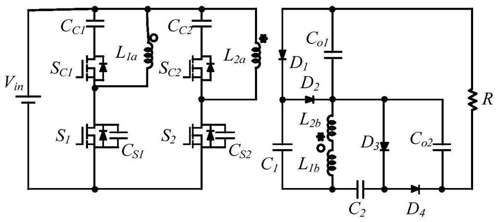
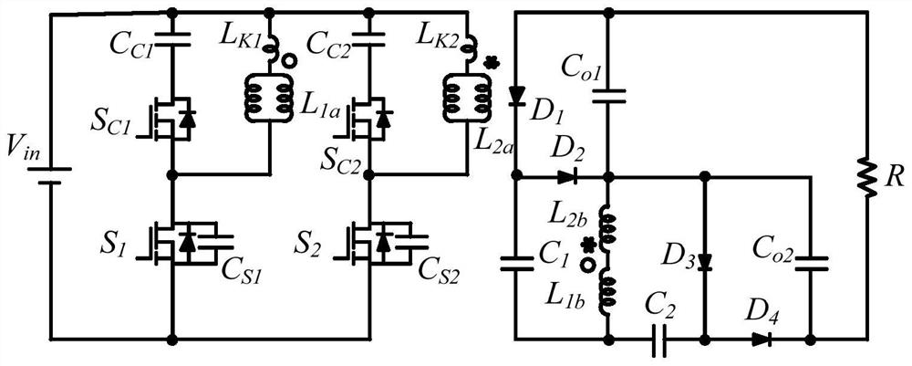
[0034] This application discloses a high-gain boost converter for photovoltaic power generation, please refer to figure 1 The high-gain boost converter for photovoltaic power generation includes an input circuit and an output circuit, and the input circuit is connected with an input power supply V in , a load R is connected to the output circuit. The Boost converter includes a coupled inductor primary winding L 1a and the coupled inductor secondary winding L 1b A set of coupled inductors formed, and the primary winding L of the coupled inductor 2a and the coupled inductor secondary winding L 2b form another set of coupled inductors. Among them, the primary winding L of the coupled inductor 1a and coupled inductor primary winding L 2a Set in the input circuit, the coupled inductor secondary winding L 1b and the coupled inductor secondar...


PUM


Abstract

The invention discloses a high-gain Boost converter for photovoltaic power generation, and relates to the field of photovoltaic technology, an input circuit of the high-gain Boost converter for photovoltaic power generation forms an interleaving parallel structure, so that the high-gain Boost converter for photovoltaic power generation can better adapt to occasions of low-voltage large-current input and high-voltage output, has excellent natural current sharing capability, and can be applied to the field of photovoltaic power generation. A first clamping circuit and a second clamping circuit are arranged in the input circuit to provide a loop for releasing leakage inductance energy of the coupling inductor, so that the voltage spike of a switching tube is reduced, the reverse recovery current of a semiconductor device can be inhibited, the efficiency of the converter is improved, and the reliability of the converter is improved. Therefore, the Boost converter has the characteristics of high voltage gain, low device stress, small switching loss, continuous input current and low current ripple, is excellent in performance, and can adapt to application requirements in the photovoltaic field.

Description

technical field [0001] The invention relates to the field of photovoltaic technology, in particular to a high-gain boost converter for photovoltaic power generation. Background technique [0002] In recent years, the fossil energy crisis and the increasing global environmental pollution have made photovoltaic power generation one of the research hotspots. More and more photovoltaic distributed generation is connected to the low-voltage distribution network through inverters. However, the output DC voltage of the photovoltaic array is lower than The input DC voltage of the grid-connected inverter, so high-efficiency and high-gain DC / DC converters are indispensable in photovoltaic power generation systems. [0003] The Boost converter is a commonly used DC / DC converter, but the traditional Boost converter has the following problems: the voltage gain is limited by parasitic parameters such as capacitance, inductance, and switching devices, and with the increase of the duty cycl...

Claims


Application Information

Patent Timeline
IPC IPC(8): H02M3/335H02M1/088H02M1/32
CPCH02M3/33569H02M1/088H02M1/32
Inventor 樊启高沈晔豪艾建毕恺韬朱一昕
Owner JIANGNAN UNIV
Learn More