Supercharge Your Innovation With Domain-Expert AI Agents!

Bidirectional BUCK/BOOST energy storage circuit for matching large dynamic load change

An energy storage circuit and load change technology, which is applied in the direction of AC network load balancing, electrical components, and adjustment of electrical variables, can solve the problems of many devices, large sizes, and large losses, and achieve less circuit devices and controllable withstand voltage Effect

Active Publication Date: 2022-07-26
SOUTHWEST CHINA RES INST OF ELECTRONICS EQUIP
View PDF9 Cites 0 Cited by
  • Summary
  • Abstract
  • Description
  • Claims
  • Application Information

AI Technical Summary

Problems solved by technology

In the unidirectional BUCK conversion energy storage method, the device utilization rate is not high and the size is large, which is not suitable for miniaturized platform applications
At the same time, for one-way transmission, there are many devices and large losses

Method used


Image

  • Bidirectional BUCK/BOOST energy storage circuit for matching large dynamic load change
  • Bidirectional BUCK/BOOST energy storage circuit for matching large dynamic load change
  • Bidirectional BUCK/BOOST energy storage circuit for matching large dynamic load change

Examples


Embodiment

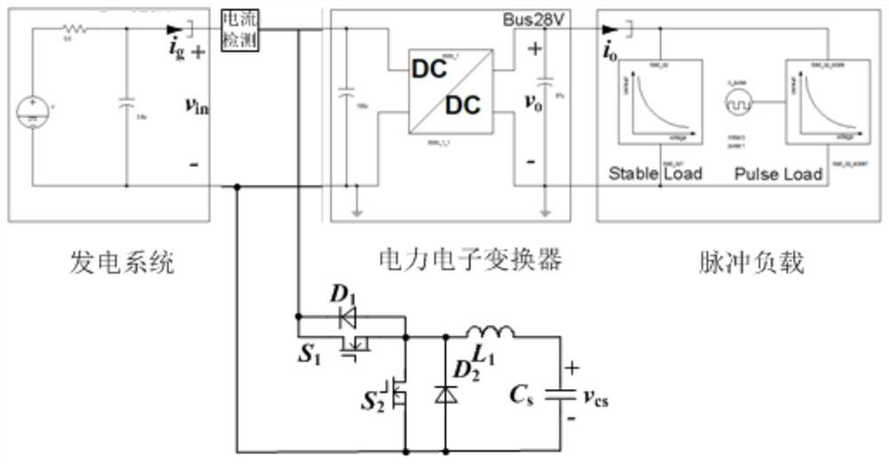
[0040] The generator of the main circuit is a three-phase 115V / 400Hz through a three-phase rectifier circuit. The input voltage range is AC108V~AC125V.

[0041] Bidirectional BUCK / BOOST energy storage circuit: MOS tube S1, MOS tube S2 and inductor L1 constitute the BUCK energy storage charging circuit and the BOOST energy releasing circuit;

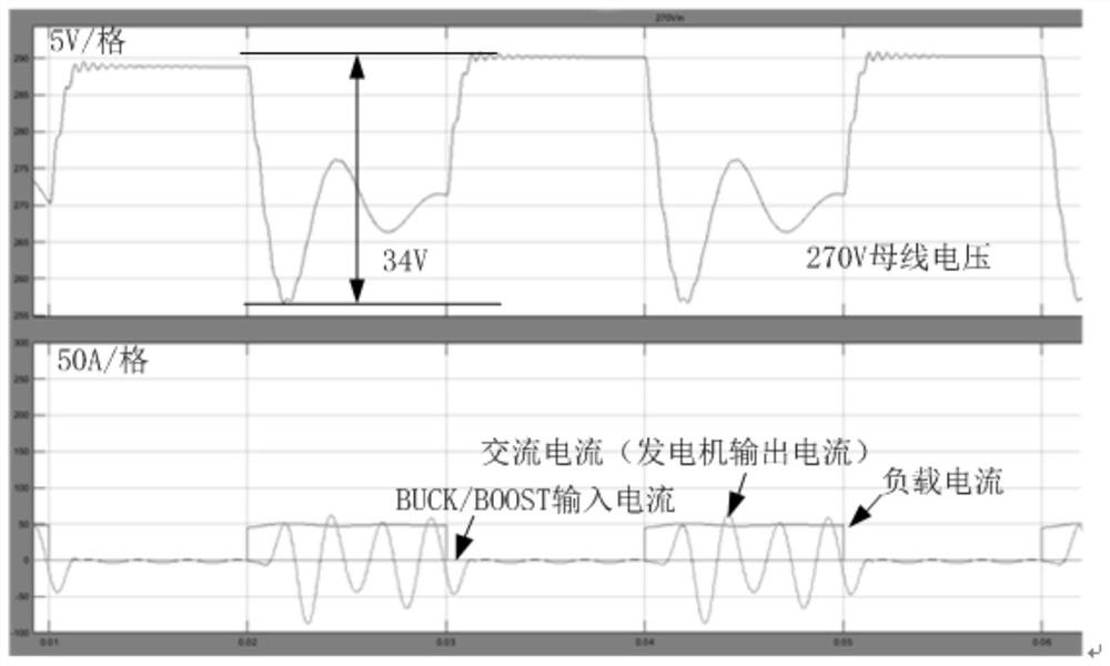
[0042] The 270V AC power from the generator is output by 18-pulse rectification and filtering, and its load dynamic characteristics are poor, that is, when the load changes dynamically, in the case of no compensation device, the current and voltage of 270Vin will change dynamically with the change of the load current. When a 13kW constant power load transient occurs in the power supply system (13kW, 50Hz, 50% duty cycle, hereinafter referred to as the standard dynamic condition), the simulation of the non-bidirectional BUCK / BOOST energy storage circuit is as follows image 3 shown. , it can be seen that the fluctuation of the AC current...


PUM


Abstract

The invention relates to the field of power supply conversion of a power supply system to a large dynamic load, and discloses a bidirectional BUCK / BOOST energy storage circuit used for matching the change of the large dynamic load, the circuit is composed of an MOS tube S1, a diode D1, an MOS tube S2, a diode D2, an inductor L and an energy storage capacitor Cs, the drain-source electrode (DS) of the MOS tube S1 is equivalently connected in parallel with the diode D1, the drain-source electrode (DS) of the MOS tube S2 is equivalently connected in parallel with the diode D2, and the inductor L is connected in parallel with the energy storage capacitor Cs. The source electrode of the MOS tube S1 is connected with the drain electrode of the MOS tube S2, driving signals of the MOS tube S1 and the MOS tube S2 are complementary, and the inductor L and the energy storage capacitor Cs are connected in series and then connected to the MOS tube S2 in parallel. Compared with the prior art, the bidirectional BUCK / BOOST energy storage circuit provided by the invention has the advantages that the energy utilization rate of the energy storage capacitor can be improved, and high efficiency is realized through single-stage conversion.

Description

technical field [0001] The invention relates to the field of power supply transformation for a power supply system to large dynamic loads, in particular to a bidirectional buck / boost energy storage circuit for matching large dynamic load changes, which is mainly used in the occasions where the output power of a power supply generator changes greatly, and the system volume requirement is relatively large. Small and high power density requirements. Background technique [0002] As the detection distance increases, the power of the transmitter increases continuously. The basic working mode of the transmitter is two modes of transmit and receive, namely T / R (Transmitter and Receiver) mode, which leads to the large dynamic change of the load on the load side of the power electronic converter with T / R as the main load. For limited and low-power power supply systems such as aircraft, unmanned aerial vehicles, automobiles, and small ships, the impact of large dynamic pulse loads on...

Claims


Application Information

Patent Timeline
Patent Type & Authority Applications(China)
IPC IPC(8): H02J3/28H02J3/24H02M3/158
CPCH02J3/28H02J3/24H02M3/1582Y02B70/10
Inventor 王斌白雷赵伟刚黄付刚张莉王海龙周旭雷志刚王辉陈根余张志伟王凤岩张斐余俊宏刘晓庆
Owner SOUTHWEST CHINA RES INST OF ELECTRONICS EQUIP
Features
  • R&D
  • Intellectual Property
  • Life Sciences
  • Materials
  • Tech Scout
  • Unparalleled Data Quality
  • Higher Quality Content
  • 60% Fewer Hallucinations
Learn More