Construction waste treatment device
A construction waste and treatment device technology, applied in the field of waste treatment, can solve the problems of troublesome operation, pollution of the surrounding environment, and high labor cost, and achieve the effects of high work efficiency, accelerated crushing efficiency, and improved crushing effect.
- Summary
- Abstract
- Description
- Claims
- Application Information
AI Technical Summary
Problems solved by technology
Method used
Image

Examples
Embodiment 1
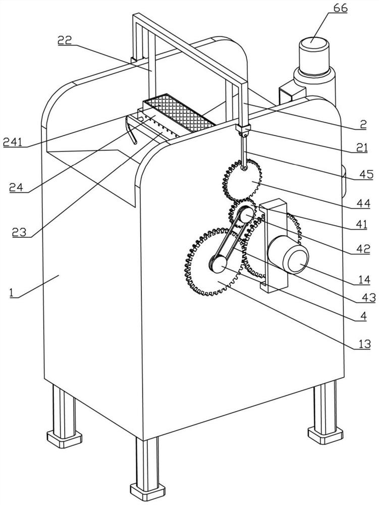
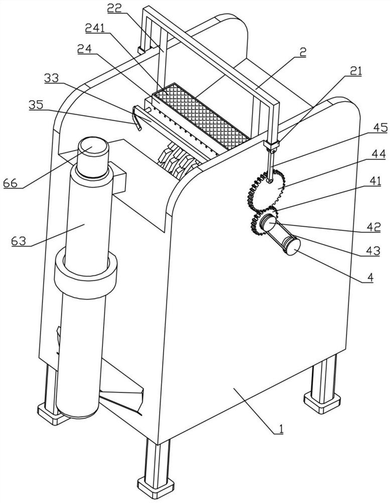
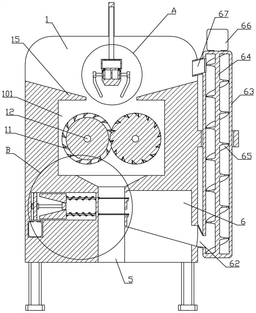
[0035] like Figure 1-6 As shown, a construction waste treatment device of the present invention includes a box body 1, a processing cavity 101 is arranged in the middle of the box body 1, and a crushing mechanism is arranged in the processing cavity 101;
[0036] The crushing mechanism includes two crushing rollers 11. The two crushing rollers 11 are rotated and assembled inside the processing chamber 101 through the rotating shaft 12. The front ends of the two rotating shafts 12 are connected with first gears 13. A gear 13 is provided with a first motor 14 , the left and right sides of the box body 1 are provided with material guide plates 15 located on the upper side of the crushing roller 11 , and the upper side of the box body 1 is also provided with a pressing material directly above the two crushing rollers 11 mechanism;
[0037] The pressing mechanism includes a U-shaped frame 2, the middle of the box 1 is provided with sliding sleeves 21 on both sides, the two end feet...
Embodiment 2
[0049] like Figure 7-9 As shown, as an improvement of the previous embodiment, the two filter plates 58 are electromagnetic filter plates, and the two electromagnetic filter plates are provided with an on-off component, and the on-off component includes a limiter disposed on the front and rear side walls of the blanking channel 5. Position slot 7, the limit slot 7 extends toward the second cavity 7 to the upper side of the fixed plate 61, the front and rear ends of the hinge seat 57 are provided with conductive rods 71 that match the limit slot 7, and the conductive rod 71 is connected to the electromagnetic filter plate. Electrically connected, a conductive sheet 72 is arranged in the limiting slot 7 , the starting end of the conducting sheet 72 is located at the left end of the limiting slot 7 , the terminal end of the conducting sheet 72 is located at the left side of the fixing plate 61 , and the lower end of the right side of the second cavity 6 There is a metal feedin...
Embodiment 3
[0052] like Figure 10-11 As shown, as an improvement of the previous embodiment, the upper end of the fixed plate 61 is provided with a trapezoidal boss 8 that matches any one group of the first filter holes 581, and the lower side of the filter plate 58 is in contact with the upper end of the trapezoidal boss 8. The length dimension of the lower bottom of the boss 8 is smaller than the diameter dimension of the first filter hole 581. The lower left end of the second cavity 7 is provided with a feeding chute 81 that communicates with the feeding channel 5. The upper end of the feeding chute 81 is open. The length dimension is smaller than the length dimension of the filter plate 58;
[0053] When the hinge seat 57 is located on the leftmost side of the feeding channel 5, the first filter hole 581 on the filter plate 58 is not aligned with the trapezoidal boss 8, when the hinge seat 57 drives the filter plate 58 toward the second cavity 6 During movement, a group of first fil...
PUM
 Abstract
Description
Claims
Application Information
 - Generate Ideas
- Intellectual Property
- Life Sciences
- Materials
- Tech Scout
- Unparalleled Data Quality
- Higher Quality Content
- 60% Fewer Hallucinations
Browse by: Latest US Patents, China's latest patents, Technical Efficacy Thesaurus, Application Domain, Technology Topic, Popular Technical Reports.
© 2025 PatSnap. All rights reserved.Legal|Privacy policy|Modern Slavery Act Transparency Statement|Sitemap|About US| Contact US: help@patsnap.com