Sludge squeezer with distributed squeezing units
A sludge press, distributed technology, applied in the direction of sludge treatment, water/sludge/sewage treatment, chemical instruments and methods, etc., can solve the problems of single structure, slow dehydration speed, poor dehydration effect, etc., and achieve increased Effects of side wall area, increased loading capacity, and improved drainage efficiency
- Summary
- Abstract
- Description
- Claims
- Application Information
AI Technical Summary
Problems solved by technology
Method used
Image

Examples
Embodiment 1
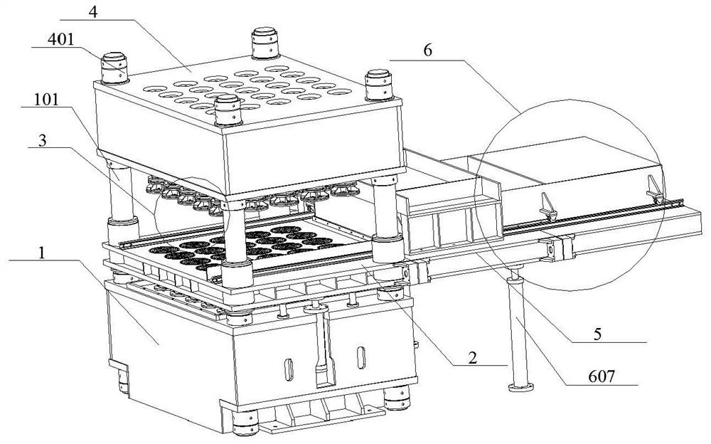
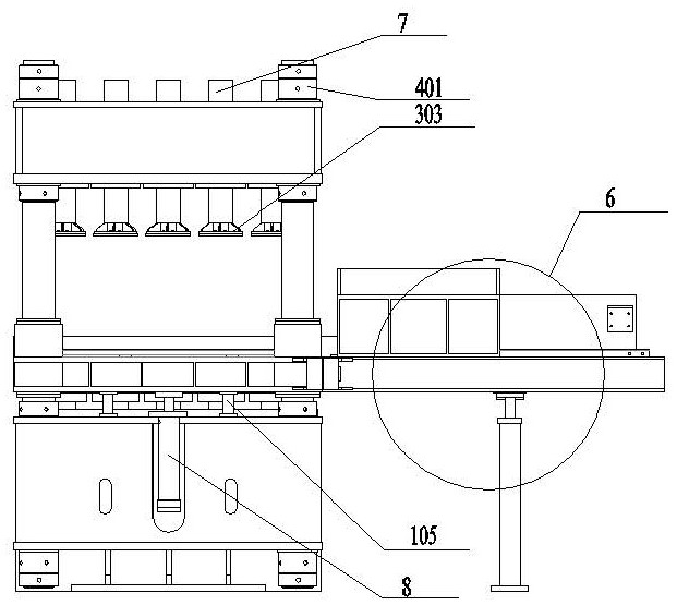
[0040] like Figure 1-10 As shown, a sludge press with distributed pressing units includes a lower platform 1 on which a plurality of groups of uprights 101 are installed to guide the sliding of the movable beam 2, and a plurality of groups of the uprights The movable beam 2 is installed on the movable beam 2, and the pressing unit 3 is penetrated in the movable beam 2. The vertical column 101 is also sleeved with a fixed beam 4, and the upper and lower ends of the fixed beam 4 are fixedly connected with adjusting nuts 401. The fixed beam 4 is limited on the upright column 101 by adjusting the nut 401 to provide structural guarantee for the orderly progress of the sludge pressing work. There is a working space, and a pressing hydraulic cylinder 7 is installed on the fixed beam 4. The pressing hydraulic cylinder 7 drives the pressing unit 3 to work to complete the sewage pressing of sludge. The pressing hydraulic cylinder 7 can also be other power drive devices;
[0041] The r...
Embodiment 2
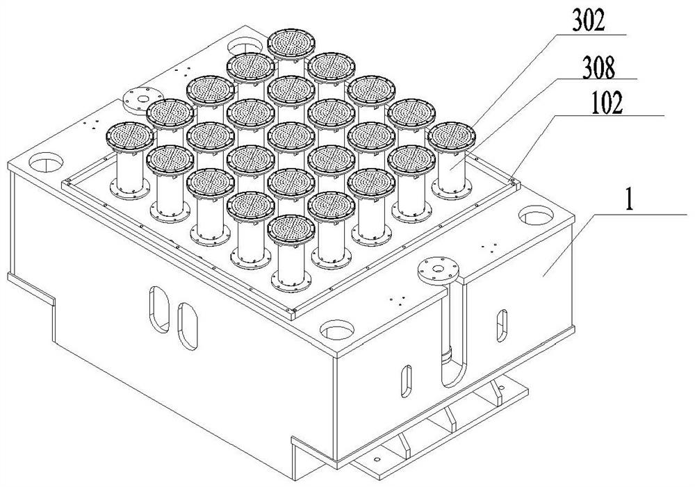
[0045] like Figure 3-5 As shown, the lower platform 1 is provided with a water blocking frame 102, the water blocking frame 102 is arranged on the lower platform 1 and multiple groups cooperate with each other to form a rectangular frame, and the sewage formed by pressing is concentrated on the inner side of the water blocking frame 102, so the The pressing unit 3 is located on the inner side of the water blocking frame 102. The lower platform 1 on the inner side of the water blocking frame 102 is provided with a plurality of groups of water outlet holes 103 on the plane. The water outlet hole 103 is connected with the sewage pipeline 104, the sewage pipeline 104 is connected to the external drainage pipeline, the sewage formed by the sludge pressing is discharged from the water outlet hole 103 to the sewage pipeline 104, and finally the staff will install the external The drainage pipe is connected to the sewage pipeline to discharge the sewage produced by pressing in time. ...
Embodiment 3
[0048] like Figure 1-7 As shown, the pressing units 3 are distributed on the movable beam 2 in multiple groups, and the pressing unit 3 includes a filter cartridge 301, the filter cartridge 301 is fixedly connected to the movable beam 2, and the bottom of the filter cartridge 301 is installed There is a lower indenter 302, an upper indenter 303 is also arranged above the lower indenter 302, a working space is left between the upper indenter 303 and the lower indenter 302, and the upper indenter 303 is connected with the lower indenter 303. There are permeable holes 306 evenly distributed on the pressure head 302, and round holes 307 are evenly distributed on the filter cartridge 301. The permeable holes 306 and the round holes 307 are used to discharge the sewage generated during the sludge pressing. The head 303 is connected with the piston rod of the pressing hydraulic cylinder 7 which is arranged in the fixed beam 4. Each pressing unit 3 corresponds to a single pressing hy...
PUM
 Abstract
Description
Claims
Application Information
 - R&D
- Intellectual Property
- Life Sciences
- Materials
- Tech Scout
- Unparalleled Data Quality
- Higher Quality Content
- 60% Fewer Hallucinations
Browse by: Latest US Patents, China's latest patents, Technical Efficacy Thesaurus, Application Domain, Technology Topic, Popular Technical Reports.
© 2025 PatSnap. All rights reserved.Legal|Privacy policy|Modern Slavery Act Transparency Statement|Sitemap|About US| Contact US: help@patsnap.com