Splicing type construction method of wall

A construction method and splicing technology, applied in building structures, protective buildings/shelters, walls, etc., can solve the problems of waste of wall panel performance, weak impact resistance, and insufficient performance of wall panels. The effect of improving construction efficiency, increasing compressive strength, and shortening wall construction time

Active Publication Date: 2022-07-29
CHINA CIVIL ENG CONSTR CORP +2
View PDF5 Cites 1 Cited by
  • Summary
  • Abstract
  • Description
  • Claims
  • Application Information

AI Technical Summary

Problems solved by technology

However, when prefabricated wall panels are installed and fixed into walls, they are generally clamped or directly connected to each other through steel bars, and then filled and fixed by cast-in-place concrete. Limited by the above connection structure, prefabricated wall panels and relative The strength that the cast-in-place concrete between the connected columns or beams can withstand will be less than the strength that the prefabricated wall panel itself can bear, resulting in a waste of wall panel performance, and the performance of the wall panel cannot be fully utilized
[0004]In addition, with the improvement of building construction standards, the seismic requirements of buildings are also increasing. In addition, the shock wave of the earthquake is a transverse wave, so it is necessary to have sufficient earthquake resistance in the vertical and horizontal directions of the wall, as well as in the longitudinal and horizontal directions; and the current wall panels, whether prefabricated or cast-in-place, have sufficient resistance to the vertical direction of the wall. Shock is always weaker

Method used


Image

  • Splicing type construction method of wall
  • Splicing type construction method of wall
  • Splicing type construction method of wall

Examples


Embodiment 1

[0138] First, manufacture the prefabricated wall panel 1 according to the construction requirements of the wall, including the following steps:

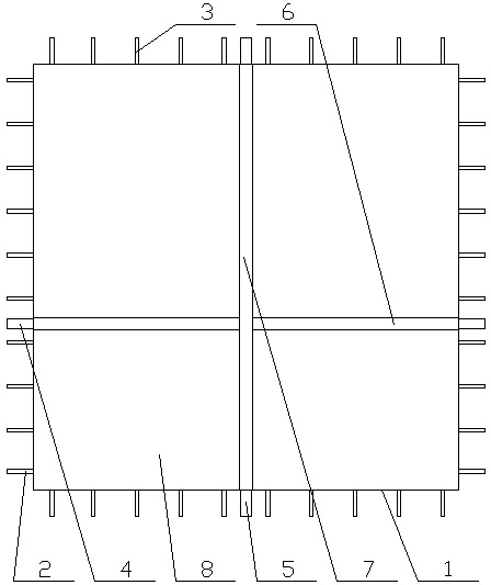
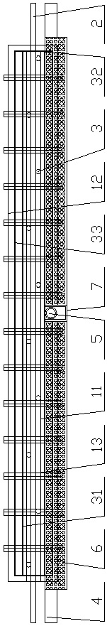
[0139] 01) The core board cage body 11 is formed by splicing and welding steel bars, and then the horizontal pretensioning ties 2, the vertical pretensioning ties 3 and the horizontal longitudinal connecting ribs 13 are respectively fixed and connected in the core board cage 11.

[0140] The vertical pre-tensioning ties 3 are respectively staggered and evenly fixed on both sides of the core board cage 11 , and the horizontal pre-tensioning ties 2 are fixedly connected to the vertical ties respectively provided on both sides of the core board cage 11 . Between the pre-tensioning ties 3, the horizontal longitudinal connecting rib 13 is perpendicular to the horizontal pre-tensioning ties 2 and the vertical pre-tensioning ties 3 respectively.

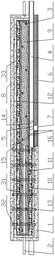
[0141] 02) Each end face of the core board cage body 11 is fixed with a pouring template, and ...


PUM


Abstract

The invention discloses a splicing type construction method of a wall body. The splicing type construction method comprises the following steps that column bodies on the two sides of the wall body are fixed to the tops of corresponding column bodies below the wall body; when the distance between the two column bodies is smaller than or equal to one meter, the two column bodies are fixedly connected through transverse ribs; when the distance between the two column bodies is larger than one meter, the tops of the adjacent lower-layer beam bodies and the two column bodies are spliced and fixed through connecting pieces and at least one prefabricated wallboard horizontal pre-tightening tie bar or vertical pre-tightening tie bar; a fixed beam body is placed on the top between the two column bodies in the extending direction of the wall body; when the distance between the two column bodies is smaller than or equal to one meter, the screw rods at the bottoms of the beam bodies are fixedly connected with the screw rods at the tops of the adjacent lower-layer beam bodies through vertical ribs; cast-in-place concrete C is conducted on the wall defined by the column bodies and the beam bodies and the area located outside the prefabricated wall panel; and after the cast-in-place concrete C is solidified, wall building and forming are completed. According to the splicing type construction method of the wall, the building construction efficiency can be improved, the wall is firm and stable, the integration effect is good, and the good anti-seismic effect is achieved.

Description

technical field [0001] The invention relates to the technical field of prefabricated wall panels splicing walls, in particular to a splicing construction method of walls. Background technique [0002] Prefabricated wall panels refer to reinforced concrete panel-type components processed in prefabrication factories (fields) or construction sites for building assembly, referred to as wall panels or wall panels. The use of prefabricated concrete wall panels to build prefabricated large-slab buildings can improve the degree of factory-like and mechanized construction, reduce on-site wet operations, save on-site labor, overcome seasonal effects, and shorten building construction periods. [0003] The current prefabricated wall panels are processed and produced in advance according to the requirements in the prefabrication factory, and many kinds of lightweight, easy-to-install, and even high-strength prefabricated wall panels can be produced. However, when the prefabricated wall...

Claims


Application Information

Patent Timeline
Patent Type & Authority Applications(China)
IPC IPC(8): E04B2/56E04B2/00E04C2/284E04C2/30E04C2/52E04B1/58E04B1/80E04B1/98E04H9/02E04G21/14B28B23/02B28B23/04B28B13/06H02G3/38H02G1/00
CPCE04B2/56E04B2/562E04B2/00E04C2/284E04C2/30E04C2/46E04C2/521E04B1/58E04B1/80E04B1/98E04H9/021E04G21/14B28B23/024B28B23/043B28B13/06H02G3/386H02G3/388H02G1/00
Inventor 张志超陈永卿朱小杰李继江王尧浩赵文银李阳
Owner CHINA CIVIL ENG CONSTR CORP
Why Eureka
Try Eureka