Hydrogen and natural gas combined liquefaction system and process

A natural gas and hydrogen technology, applied in the field of hydrogen and natural gas combined liquefaction system, can solve the problems of low liquefaction efficiency and high cost, and achieve the effects of improving the environment, compact structure and reducing carbon emissions

Pending Publication Date: 2022-07-29
CHINA UNIV OF PETROLEUM (BEIJING)
View PDF4 Cites 1 Cited by
  • Summary
  • Abstract
  • Description
  • Claims
  • Application Information

AI Technical Summary

Problems solved by technology

[0004] In view of the above problems, the object of the present invention is to provide a combined liquefaction system and process of hydrogen and natural gas. The system and process adopt a mixed refrigerant cycle system and process that are connected in series first and then paralleled to realize efficient combined liquefaction of hydrogen and natural gas, achieving The purpose of simplifying the process, reducing energy consumption, saving space and equipment investment can solve the technical problems of low liquefaction efficiency and high cost in the storage and transportation of liquid hydrogen and LNG

Method used


Image

  • Hydrogen and natural gas combined liquefaction system and process
  • Hydrogen and natural gas combined liquefaction system and process
  • Hydrogen and natural gas combined liquefaction system and process

Examples


Embodiment 1

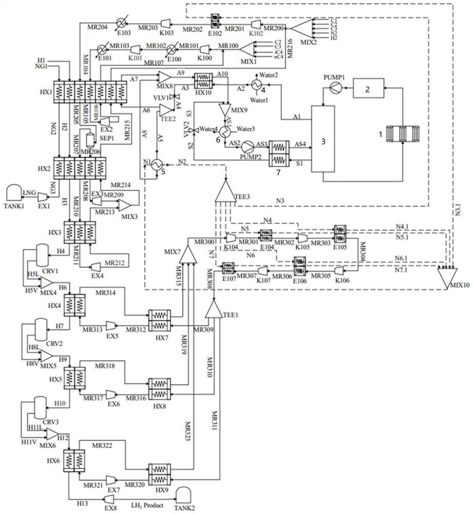
[0084] This embodiment provides a combined liquefaction system for hydrogen and natural gas, the structure of which is as follows figure 1 shown.

[0085] The system includes: DMR pre-cooling unit, solar absorption refrigeration unit, J-B cryogenic unit, expansion liquefaction unit, natural gas liquefaction pipeline, and hydrogen liquefaction pipeline; wherein,

[0086] The DMR pre-cooling unit includes a series-connected primary countercurrent heat exchanger HX1, secondary countercurrent heat exchanger HX2, tertiary countercurrent heat exchanger HX3, second expander EX2, gas-liquid separator SEP1, and third expander EX3 , the third mixer MIX3, the fourth expander EX4, the first Brayton cycle and the second Brayton cycle in series;

[0087] The first-stage countercurrent heat exchanger HX1 is provided with seven flow passages, the second-stage countercurrent heat exchanger HX2 is provided with five flow passages, and the third-stage countercurrent heat exchanger HX3 is provid...

Embodiment 2

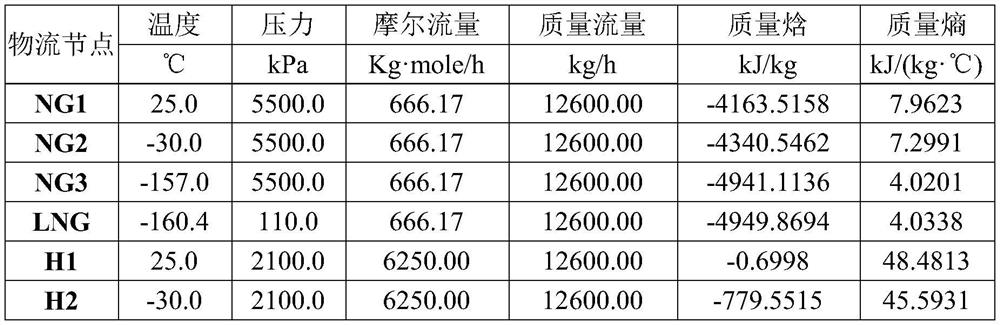
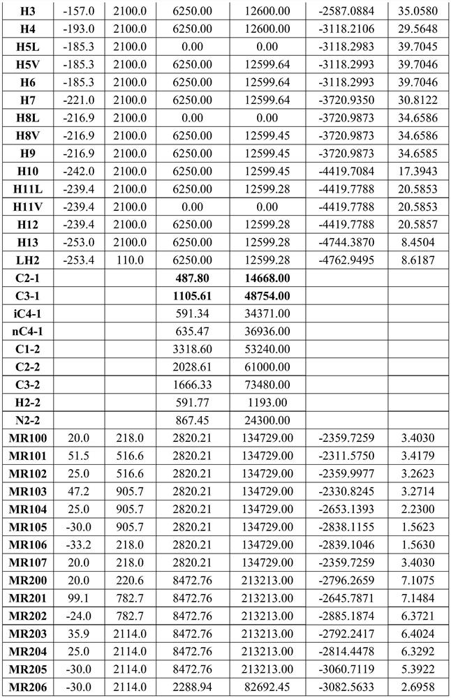
[0134] This embodiment provides a combined liquefaction process of hydrogen and natural gas, which is carried out by using the system provided in Embodiment 1, and specifically includes the following steps:

[0135] The refrigeration cycle of the DMR pre-cooling unit includes the following process steps:

[0136] The DMR precooling unit consists of two independent mixed refrigerant (MR1 and MR2) Brayton cycles in series, which together provide cold energy for precooling and subcooling natural gas and precooling hydrogen. The inner cycle MR1 and the outer cycle MR2 use different mixed refrigerants respectively. The MR1 refrigerant (ie the first refrigerant) is composed of 17.3% C2 , 39.2%C 3 , 20.97% iC 4 and 22.53% nC 4 Composition (molar percent), MR2 refrigerant (ie, the second refrigerant) consists of 39.17% C 1 , 23.94%C 2 , 19.67%C 3 , 10.24%N 2 and 6.98%H 2 Composition (mol%);

[0137] The MR1 circulating refrigerant (MR100) is first pressurized to 9.057bar by th...


PUM


Abstract

The invention provides a hydrogen and natural gas combined liquefaction system and process. The system comprises a DMR precooling unit, a refrigeration unit, a J-B cryogenic unit, an expansion liquefaction unit, a natural gas liquefaction pipeline and a hydrogen liquefaction pipeline. The DMR precooling unit is coupled with the refrigeration unit through a first-stage countercurrent heat exchanger; the DMR pre-cooling unit is connected with the J-B deep cooling unit through a first-stage ortho-parahydrogen converter; the natural gas liquefaction pipeline sequentially penetrates through the first-stage countercurrent heat exchanger and the second-stage countercurrent heat exchanger and is connected to the natural gas expansion machine. A hydrogen liquefaction pipeline sequentially penetrates through the first-stage countercurrent heat exchanger, the second-stage countercurrent heat exchanger, the third-stage countercurrent heat exchanger, the first-stage ortho-para hydrogen converter, the fourth-stage countercurrent heat exchanger, the second-stage ortho-para hydrogen converter, the fifth-stage countercurrent heat exchanger, the third-stage ortho-para hydrogen converter and the sixth-stage countercurrent heat exchanger and is connected to a hydrogen expansion machine. The invention further provides a hydrogen and natural gas combined liquefaction process adopting the system.

Description

technical field [0001] The invention belongs to the technical field of natural gas liquefaction, and particularly relates to a combined liquefaction system and process of hydrogen and natural gas. Background technique [0002] LNG is an important form of natural gas storage and transportation. It is not only an important means of importing natural gas, but also an indispensable technical means for developing remote and scattered gas field resources. At the same time, the hydrogen energy industry has begun to flourish, and storage and transportation issues are the key to restricting the large-scale development of hydrogen energy. Similar to the development route of natural gas, liquid hydrogen storage and transportation is also expected to occupy a very important position in the future. Natural gas and hydrogen have similar properties and belong to both clean energy sources. In the future, the two will develop in parallel, complement each other's advantages, and play an impo...

Claims


Application Information

Patent Timeline
Patent Type & Authority Applications(China)
IPC IPC(8): F25J1/02
CPCF25J1/001F25J1/0022F25J1/0257F25J1/0042F25J1/005F25J1/0057F25J1/0052F25J1/0055F25J1/0236F25J2270/16F25J1/0265F25J1/0242F25J2230/04F25J1/0092F25J1/0062F25J1/0217F25J2260/30F25J2270/906F25J1/0227F25J1/0297
Inventor 左丽丽耿金亮孙恒王超
Owner CHINA UNIV OF PETROLEUM (BEIJING)
Why Eureka
Try Eureka