
Anisotropy compensation MUSIC damage imaging method based on excitation focusing scanning

An anisotropic, imaging method, applied in instruments, measuring devices, analyzing solids using sonic/ultrasonic/infrasonic waves, etc., can solve problems such as enhancement, and achieve the effect of improving positioning accuracy and signal-to-noise ratio.

Pending Publication Date: 2022-07-29
NANJING UNIV OF POSTS & TELECOMM
View PDF0 Cites 0 Cited by
  • Summary
  • Abstract
  • Description
  • Claims
  • Application Information

AI Technical Summary

Problems solved by technology

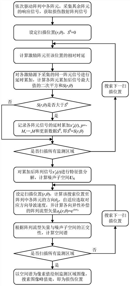
[0005] The purpose of the present invention is to overcome the defects of the prior art and provide an anisotropy-compensated MUSIC damage imaging method based on excitation focus scanning, aiming at serious propagation attenuation of guided waves on strongly attenuating anisotropic structures and obvious speed differences in all directions As a result, the accuracy of the MUSIC imaging method is reduced. Taking advantage of the characteristics that the piezoelectric sensor can be used as a driver or a sensor, the excitation focusing scanning mechanism of a one-dimensional linear array is introduced, so that the excitation signal of each array element in the array is focused on the damage. position, so as to enhance the amplitude of the damage scattering signal and improve its signal-to-noise ratio; secondly, using the pre-measured guided wave velocities in all directions on the structure, the dual anisotropic compensation mechanism of scanning direction-array element direction is adopted, during the MUSIC scanning process Adaptively correct the array flow pattern vector and compensate the array error introduced by structural anisotropy, which can effectively improve the positioning imaging accuracy and reliability of the MUSIC damage imaging method in strong attenuation anisotropic structures

Method used


Image

  • Anisotropy compensation MUSIC damage imaging method based on excitation focusing scanning
  • Anisotropy compensation MUSIC damage imaging method based on excitation focusing scanning
  • Anisotropy compensation MUSIC damage imaging method based on excitation focusing scanning

Examples


Embodiment 2

[0086] Example 2 of the present invention: using a carbon fiber composite material plate as a strong attenuation anisotropic structure to conduct a damage localization experiment to illustrate its specific implementation process.

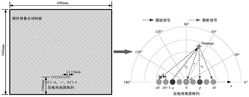
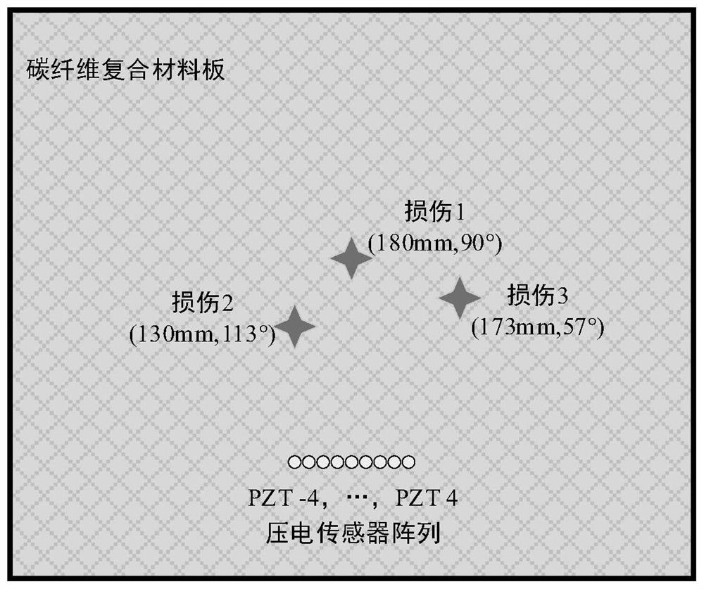
[0087] like figure 2 As shown, the size of the carbon fiber composite material board is 600mm×500mm×4mm, with a total of 24 layers. The thickness of each layer is 0.125mm, and the layering sequence is [45 / 0 / -45 / 90 / 0 / -45 / 0 / -45 / 0]s. A one-dimensional uniform linear array is arranged on the structure, including 9 array elements, the array element spacing is 13mm, and the names of each array element are PZT-4 to PZT 4. A polar coordinate system is established with the center of the array, namely PZT0, as the origin. At the same time, three damages were artificially simulated successively by pasting wave absorbing glue on the composite board, namely damage 1, damage 2 and damage 3. The locations of the three injuries are (180mm, 90°), (130mm, 113°) a...


PUM


Abstract

The invention discloses an anisotropic compensation MUSIC damage imaging method based on excitation focusing scanning, and the method comprises the steps: employing a self-excitation self-sensing piezoelectric sensor array to carry out the focusing scanning of an array excitation signal, and improving the signal-to-noise ratio of a damage scattering signal, aiming at the problem of low imaging precision of a strong attenuation anisotropic structure; the method comprises the following steps of: adaptively correcting an array direction vector in a MUSIC scanning process by utilizing a pre-measured guided wave propagation speed in each direction and adopting a dual anisotropic compensation mechanism of a scanning direction and an array element direction; excitation focusing scanning and a MUSIC algorithm are combined, and final damage imaging positioning is achieved. The method improves the signal-to-noise ratio of damage scattering array signals, compensates array errors caused by structural anisotropy, and has a wide application prospect in damage imaging positioning of a strong-attenuation anisotropic structure.

Description

technical field [0001] The invention belongs to the technical field of engineering structure health monitoring, and particularly relates to an anisotropic compensation MUSIC damage imaging method based on excitation focus scanning. Background technique [0002] Advanced composite material technology, especially high-strength carbon fiber composite material technology, is a typical military-civilian dual-use and military-civilian integration technology. In recent years, the trend of diversification and multi-application development is very obvious. The application fields include aerospace, wind power generation, ships, automobiles industry and many other fields. Composite structures are susceptible to low-speed impact during manufacturing and service, resulting in internal damage to the structure. These internal damages not only greatly reduce the structural strength, but also cannot be detected by conventional testing methods, making the structure a serious safety hazard. T...

Claims


Application Information

Patent Timeline
IPC IPC(8): G01N29/06G01N29/24
CPCG01N29/069G01N29/2437G01N2291/0289
Inventor 鲍峤钱晓亮王强胡伟伟
Owner NANJING UNIV OF POSTS & TELECOMM
Learn More