Noise reduction control method and system for switched reluctance motor

A technology of switched reluctance motor and control method, which is applied in control system, AC motor control, torque ripple control, etc., and can solve problems such as incomplete establishment of turn-on phase torque, large air and mechanical noise, large torque ripple, etc. , to achieve the effect of continuously adjustable speed, strong versatility, and good load adaptability

Pending Publication Date: 2022-07-29
甄鹏 +1
View PDF0 Cites 1 Cited by
  • Summary
  • Abstract
  • Description
  • Claims
  • Application Information

AI Technical Summary

Problems solved by technology

[0004] Since the switched reluctance motor uses the mechanism of the reluctance effect, the winding inductance of the switched reluctance motor changes nonlinearly with the position of the rotor, and the total output electromagnetic torque is the synthesis of the winding torque of each phase, and the torque of each phase is related to this The stator inductance of the phase winding is related to the current, which is nonlinear, so there is a large torque ripple, so there is a large air and mechanical noise during operation
[0005] The torque ripple of the switched reluctance motor mainly comes from the commutation process. During the commutation process, the off-phase current decreases slowly exponentially, and its torque decreases sharply; while the on-phase torque is not fully established, the total There is a large sag in the output torque, especially under heavy load conditions in the medium and low speed range, the torque fluctuation is even greater

Method used


Image

  • Noise reduction control method and system for switched reluctance motor
  • Noise reduction control method and system for switched reluctance motor
  • Noise reduction control method and system for switched reluctance motor

Examples


Embodiment 1

[0078] Embodiment 1 of the present invention selects a switched reluctance motor with 6 slots in the stator and 4 teeth in the rotor as the test object, hereinafter referred to as a switched reluctance motor or a test motor.

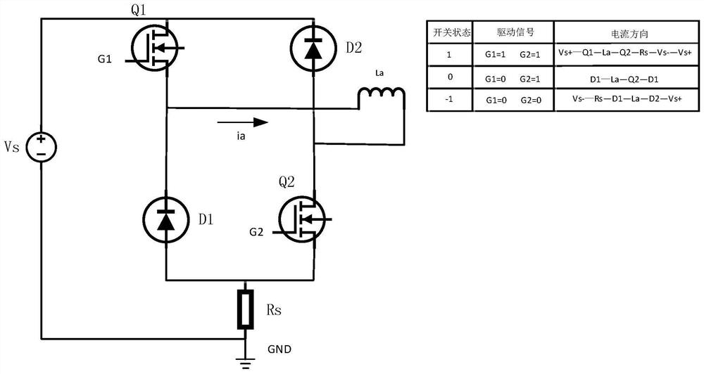
[0079] 1. If figure 1 Shown is the schematic diagram of the power switch tube applied to the one-phase winding drive control of the switched reluctance motor of this patent, which is defined as a power asymmetric H-bridge. In the figure, Q1 and Q2 are power MOS tubes, which are used to pass the power supply V s To the switched reluctance motor winding L a power supply, D1 and D2 are switched reluctance motor winding freewheeling diodes, R s is the sampling resistance of the switched reluctance motor winding. Defining the switched reluctance motor winding L a three working states: 1, 0, -1, other windings are equivalent, as follows:

[0080] ① "1" state: switched reluctance motor winding L a Power is supplied, Q1 and Q2 are turned on, and the curren...


PUM


Abstract

The invention discloses a switched reluctance motor noise reduction control method and system, and the method comprises the steps: controlling the operation of a switched reluctance motor through adjusting a commutation angle and voltage; a mode of combining torque control and commutation control of the switched reluctance motor is adopted, and the switch excitation state of each phase of the switched reluctance motor is dynamically adjusted by controlling the total torque output by the switched reluctance motor in real time; the dynamically adjusted commutation torque ripple of each phase switch is reduced, and the air noise and mechanical vibration of the operation of the switched reluctance motor are reduced accordingly, so that the total torque ripple is in a preset range. According to the scheme, the torque control characteristic of the switched reluctance motor is optimized aiming at the inherent commutation torque pulsation problem of the switched reluctance motor, so that the air noise of the operation of the switched reluctance motor is reduced, and the high-frequency mechanical jitter of the operation of the switched reluctance motor is reduced.

Description

technical field [0001] The invention relates to the technical field of switched reluctance motor control, in particular to a noise reduction control method and system for a switched reluctance motor. Background technique [0002] The switched reluctance motor is a new type of speed-regulating motor that utilizes the reluctance effect. The speed-regulating system is generally based on an H-bridge circuit composed of power electronic power switch tubes, and a single H-bridge is the one-phase drive of the switched reluctance motor; its It has the advantages of wide speed regulation range of DC system and low cost of AC system and wide application range. It is a new generation of stepless speed regulation system following AC variable frequency speed regulation system and brushless DC motor speed regulation system. The motor system composed of switched reluctance motor has a wide speed regulation range and excellent speed regulation performance. The speed regulation system has no...

Claims


Application Information

Patent Timeline
Patent Type & Authority Applications(China)
IPC IPC(8): H02P6/10H02P6/15H02P25/098
CPCH02P6/10H02P6/153H02P25/098
Inventor 盛超甄鹏
Owner 甄鹏
Why Eureka
Try Eureka