
Combined type combined denitration equipment for sintering flue gas treatment and implementation method of combined type combined denitration equipment

A sintering flue gas and composite technology, applied in the direction of separation methods, chemical instruments and methods, mixers, etc., can solve the problems of small spraying range, affecting the processing structure, and poor processing efficiency, so as to improve the reduction efficiency and improve the flue gas Effect of improving purity and uniformity

Pending Publication Date: 2022-08-02
MAANSHAN SHUNDA ENVIRONMENTAL PROTECTION EQUIP
View PDF10 Cites 2 Cited by
  • Summary
  • Abstract
  • Description
  • Claims
  • Application Information

AI Technical Summary

Problems solved by technology

[0003] The existing denitrification equipment sprays the treatment agent at a fixed angle, resulting in a small spraying range and uneven spraying, resulting in poor treatment efficiency;
[0004] Secondly, when the existing denitrification equipment is in contact with the flue gas for a long time, it is easy to block the nozzle hole, resulting in the inability to spray the atomized reactant, which affects the treatment structure

Method used


Image

  • Combined type combined denitration equipment for sintering flue gas treatment and implementation method of combined type combined denitration equipment
  • Combined type combined denitration equipment for sintering flue gas treatment and implementation method of combined type combined denitration equipment
  • Combined type combined denitration equipment for sintering flue gas treatment and implementation method of combined type combined denitration equipment

Examples


Embodiment approach

[0043] An implementation method of a composite combined denitration equipment for sintering flue gas treatment, comprising the following steps:

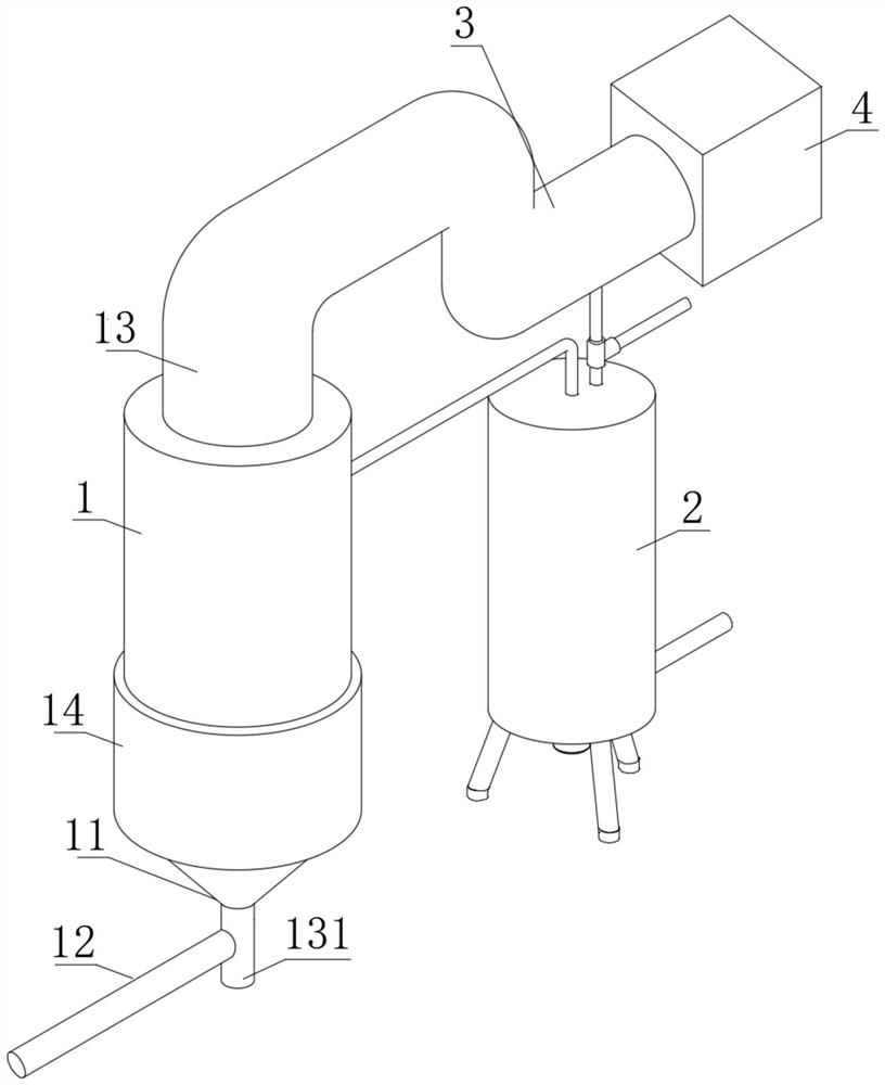
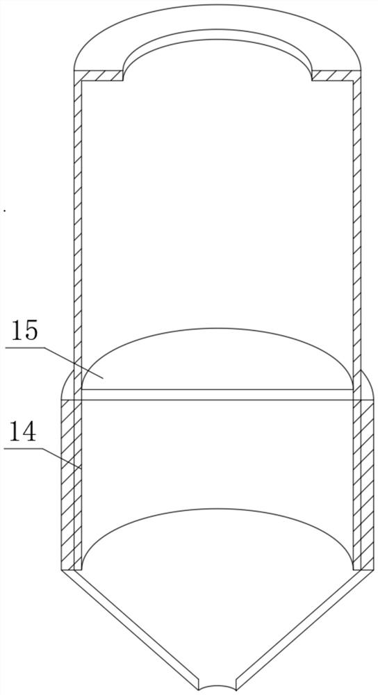
[0044] Step 1: The flue gas conveyed by the flue gas conveying pipe 12 processed through the flue gas inlet 11 is sent into the boiler 14 for heating, and the heated flue gas passes through the impurity filter screen 15 to filter out the particulate impurities and then enters the out-of-stock reaction tank 1 In the tank, effectively remove internal particulate impurities and improve the purity of flue gas;

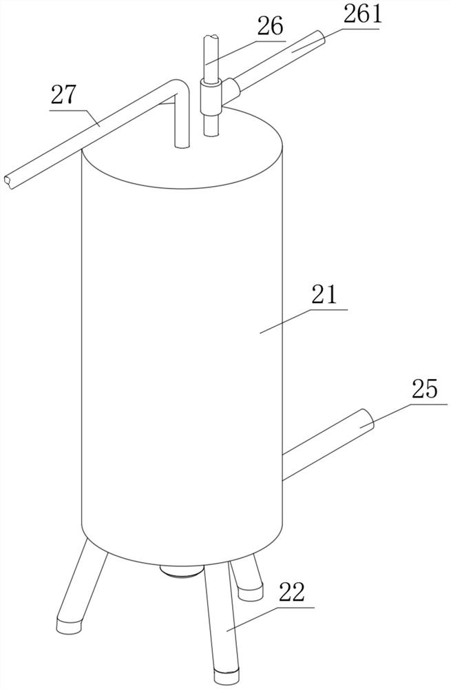
[0045] Step 2: Ammonia gas is injected into the storage tank 21 through the gas injection pipe 25, softened water is added through the water injection pipe 261, the screw agitator 24 is driven to rotate by the stirring motor 23, and the ammonia gas and the softened water are mixed and diluted to form a reducing agent. The shower assembly 27 is sprayed into the destocking reaction tank 1 to react with the flue gas, so that the amm...


PUM


Abstract

The invention discloses composite combined denitration equipment for sintering flue gas treatment and an implementation method of the composite combined denitration equipment, and belongs to the technical field of sintering flue gas treatment.The composite combined denitration equipment comprises a denitration reaction tank, a flue gas inlet is formed in the bottom end of the denitration reaction tank and connected with a flue gas conveying pipe, and a denitration assembly is arranged in the denitration reaction tank. According to the combined type combined denitration equipment for sintering flue gas treatment and the implementation method of the combined type combined denitration equipment, internal particle impurities are effectively removed, the flue gas purity is improved, the spraying positions of the spraying pipes are adjusted, the multiple sets of spraying pipes are arranged in a surrounding and dispersing mode with the connecting pipeline as the center, the spraying uniformity is effectively improved, it is guaranteed that flue gas makes contact with a reducing agent, and the reduction efficiency is improved; and the scraping bristles clean the spraying surface of the atomizing nozzle, and through internal and external cleaning, the spraying quality of the atomizing nozzle is effectively guaranteed, spraying holes are prevented from being blocked, the atomizing quality is improved, internal water vapor is effectively collected, water resource utilization is improved, repeated utilization can be achieved, and energy waste is reduced.

Description

technical field [0001] The invention relates to the technical field of sintering flue gas treatment, in particular to a compound combined denitration equipment for sintering flue gas treatment and an implementation method thereof. Background technique [0002] Desulfurization and denitrification is one of the important technical measures to prevent and control air pollution. In order to prevent excessive NOx pollution from the combustion of coal in the boiler, denitration treatment of coal should be carried out. It is divided into pre-combustion denitration, combustion process denitration, and post-combustion denitration. According to the formation mechanism of nitrogen oxides in cement kilns, there are two types of technical measures for reducing nitrogen and emission reduction in cement kilns: one is to control them from the source. The other type is governance from the end. [0003] The existing denitration equipment sprays the treatment agent at a fixed angle, resultin...

Claims


Application Information

Patent Timeline
Patent Type & Authority Applications(China)
IPC IPC(8): B01D53/78B01D53/56B01D53/00B01D46/10B01D53/04B01D46/64B01D46/681B01F27/91
CPCB01D53/78B01D53/56B01D53/002B01D46/10B01D53/04B01D46/0036B01D2258/0283B01D2251/2062Y02P10/25
Inventor 王春保金芝林超
Owner MAANSHAN SHUNDA ENVIRONMENTAL PROTECTION EQUIP
Learn More