
Multifunctional bus testing device

A bus test and multi-functional technology, applied in the field of data link test, can solve the problems such as difficult to meet the demand scene of bus test, difficult general equipment function test coverage, and insufficient test scenes, so as to achieve rich test scenes, rich display information, The effect of improving development efficiency

Pending Publication Date: 2022-08-02
XI AN JIAOTONG UNIV
View PDF1 Cites 0 Cited by
  • Summary
  • Abstract
  • Description
  • Claims
  • Application Information

AI Technical Summary

Problems solved by technology

[0002] At present, there are many types of bus test equipment commonly used in the market, such as CAN bus, 422 serial bus, 485 serial bus and other test equipment, etc., generally only can complete a single bus function, performance tests such as transmission correctness, and cannot be provided by a single device A solution for synchronous testing of multiple buses; secondly, there are fewer general-purpose devices for TLK2711 high-speed dedicated protocol data communication testing, and it is difficult to meet the demand scenarios for such bus testing; in addition, it is difficult to test the customized requirements for a certain type of data link product Functional test coverage using common devices
[0003] Patent application CN205901768U is a multifunctional bus device testing device, including a main control board, a test button module and an analog indicator board for connecting to the bus device to be tested, which satisfies the test requirements of different bus devices to a certain extent, but it adopts stm32 embedded Type chip, insufficient real-time processing capability, and insufficient test scenarios

Method used


Image

  • Multifunctional bus testing device

Examples


Embodiment Construction

[0022] The present invention will be further described in detail below with reference to the accompanying drawings. It should be understood that the specific embodiments described herein are only used to explain the present invention, and are not intended to limit the present invention.

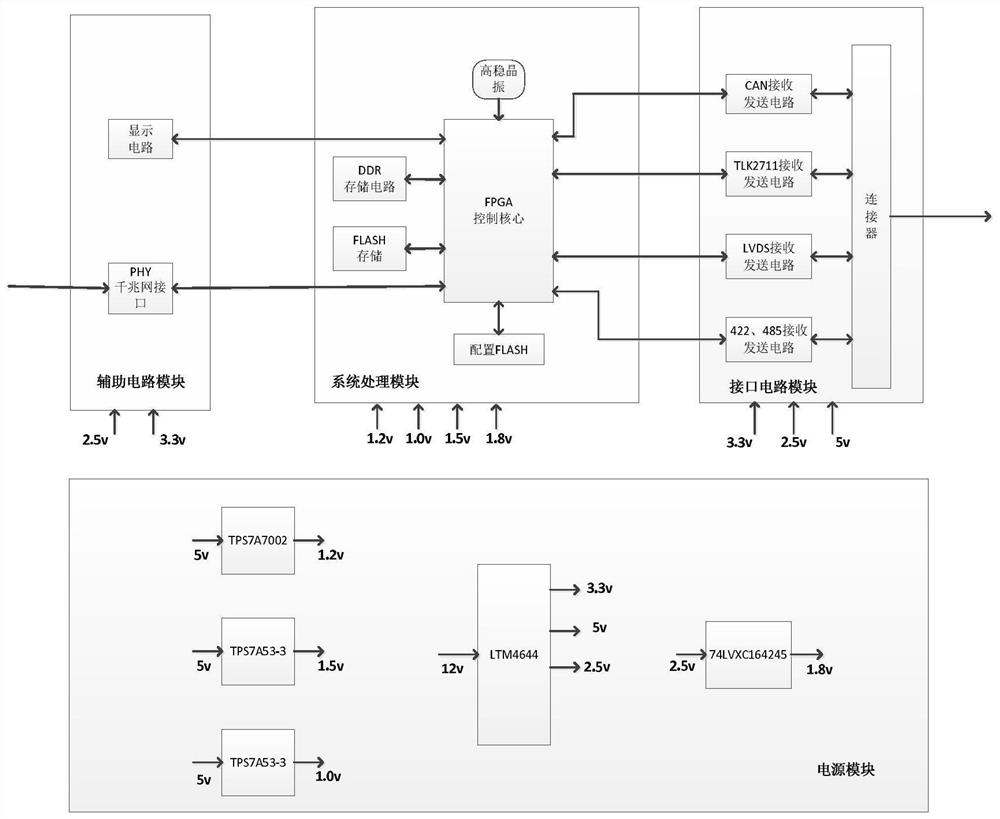
[0023] like figure 1 , a multifunctional bus test device, which consists of four main modules, namely auxiliary circuit module, system processing module, interface circuit module and power supply circuit module.

[0024] The auxiliary circuit module is composed of a display circuit and a PHY Gigabit network circuit, which completes the high-speed reception of the external source data, and realizes the real-time display and alarm of the correctness judgment result of the bus transmission data. The display circuit uses the UG2832HSWEG04OLED display, which can support 128*32 Display array, the FPGA control core outputs control signals such as chip select CS, data command control command D / C, con...


PUM


Abstract

A multifunctional bus testing device comprises a system processing module, an interface circuit module, an auxiliary circuit module and a power module, the system processing module is composed of an FPGA core circuit, an FPGA control core, a storage circuit, a clock circuit and a configuration circuit, and the functions of receiving, protocol framing, splitting and the like of various bus data are achieved; the interface circuit module comprises a CAN (Controller Area Network) bus, a TLK2711 high-speed bus and an LVDS (Low Voltage Differential Signaling) transmission bus and is used for completing the functions of rate setting, parameter configuration and verification of various buses; the auxiliary circuit module comprises a display circuit and a PHY gigabit network interface circuit, the display circuit is mainly used for displaying a bus protocol data correctness judgment result, and the PHY gigabit network interface circuit is used for receiving external data source data and sending the external data source data to the FPGA control core through a gigabit network port; the power supply module provides various secondary electric signals for the whole system; according to the invention, receiving and sending of various bus protocol data can be realized, protocol unpacking, data interpretation and interpretation result display can be carried out on the received various bus data, good support can be provided for product testing, and the method has the advantages of high efficiency, convenience and rapidness.

Description

technical field [0001] The invention relates to the technical field of data link testing, in particular to a multifunctional bus testing device. Background technique [0002] At present, there are many kinds of general bus test equipment on the market, such as CAN bus, 422 serial port bus, 485 serial port bus and other test equipment, etc., generally only a single bus function, transmission correctness and other performance tests can be completed, which cannot be provided by one device. A variety of bus synchronization test solutions; secondly, there are fewer general-purpose devices for TLK2711 high-speed dedicated protocol data communication testing, and it is difficult to meet the demand scenarios for such bus testing; in addition, it is difficult to test customized requirements for a certain type of data link product. Functional test coverage using generic devices. [0003] Patent application CN205901768U A multi-function bus device testing device, including a main cont...

Claims


Application Information

Patent Timeline
IPC IPC(8): G06F11/22
CPCG06F11/221Y02D10/00
Inventor 王明伟李铭黄宝娟李党超杨荣张育林
Owner XI AN JIAOTONG UNIV
Learn More