Friction material adding device and friction material adding method

A friction shaft and friction part technology, applied in the field of solid-phase additive, can solve the problems of coarse grains, large deformation, low additive efficiency, etc., and achieve excellent organizational properties, small deformation, and high additive efficiency of the additive layer. Effect

Pending Publication Date: 2022-08-05
CHINA-UKRAINE INST OF WELDING GUANGDONG ACAD OF SCI
View PDF10 Cites 0 Cited by
  • Summary
  • Abstract
  • Description
  • Claims
  • Application Information

AI Technical Summary

Problems solved by technology

However, the traditional additive methods are all melting additives, which have disadvantages such as pores, coarse structure grains, large deformation and low additive efficiency.

Method used


Image

  • Friction material adding device and friction material adding method
  • Friction material adding device and friction material adding method
  • Friction material adding device and friction material adding method

Examples


Embodiment 1

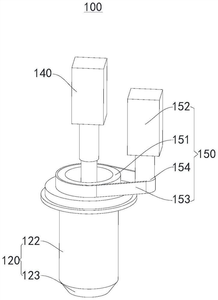
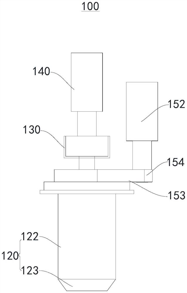
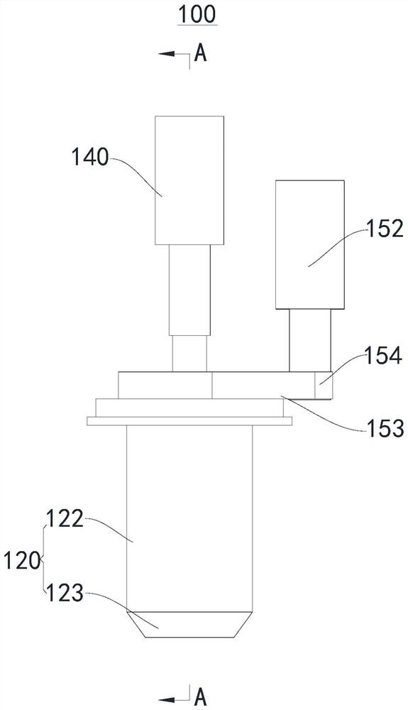
[0034] see Figure 1-Figure 4 , the present invention provides a friction additive device 100 , including a friction shaft 110 , a friction shaft sleeve 120 , a pushing mechanism 130 , a first driving mechanism 140 and a second driving mechanism 150 .

[0035] Please refer to figure 1 and Figure 4 , in this application, the friction shaft 110 is used as the main stirring shaft, which includes a clamping part 111, a friction part 112 and a material guiding part 113 connected in sequence from top to bottom. The driving mechanism 140 is connected, the diameter of the friction part 112 is larger than the diameter of the clamping part 111 and gradually increases along the direction from the clamping part 111 to the guide part 113 to form a trapezoidal structure in cross section, and the diameter of the guide part 113 is along the clamping part 113. The direction from the portion 111 to the material guide portion 113 is gradually reduced to form an inverted trapezoidal structure ...

Embodiment 2

[0042] The present embodiment provides a friction additive method, which includes using the friction additive device 100 provided in Embodiment 1 to perform friction additive on a substrate, using 6061 aluminum alloy as a raw material for additive additive, and realizing three or more layers of additive additive. material effect.

[0043] Specifically, the friction additive method provided in this embodiment includes the following steps:

[0044] Step 1: Fix the 6061 aluminum alloy substrate on the worktable, set the friction additive device 100 and the substrate at an angle of 3°, move the pushing mechanism 130 to be separated from the accommodating cavity 121, and move the friction additive device 100 above the substrate 3mm.

[0045] Step 2: Fill the 6061 aluminum alloy particles into the accommodating cavity 121. After the filling is completed, the pushing mechanism 130 is driven to push the material downward, and the first driving mechanism 140 and the second driving mec...

Embodiment 3

[0050] This embodiment provides a friction additive method, which includes using the friction additive device 100 provided in Example 1 to perform friction additive on a substrate, using T2 red copper as a raw material for additive, and realizing more than 5 layers of additive Effect.

[0051] Specifically, the friction additive method provided in this embodiment includes the following steps:

[0052] Step 1: Fix the 6061 aluminum alloy substrate on the worktable, set the friction additive device 100 and the substrate at an angle of 3°, move the pushing mechanism 130 to be separated from the accommodating cavity 121, and move the friction additive device 100 above the substrate 5mm.

[0053] Step 2: Fill the T2 copper particles into the accommodating cavity 121. After the filling is completed, the pushing mechanism 130 is driven to push the material downward, and the first driving mechanism 140 and the second driving mechanism 150 are activated respectively, and the rotationa...


PUM


Abstract

The invention provides a friction material adding device and a friction material adding method, and relates to the technical field of solid phase material adding. The friction material adding device comprises a friction shaft, a material pushing mechanism, a friction shaft sleeve, a first driving mechanism and a second driving mechanism, the friction shaft sleeve is arranged on the outer side of the friction shaft in a sleeving mode, the friction shaft sleeve and the friction shaft are coaxially arranged to form a containing cavity, and the material pushing mechanism and the friction shaft are coaxially arranged and the friction shaft penetrates through the material pushing mechanism; the material pushing mechanism can selectively move up and down inside and outside the containing cavity, the first driving mechanism is connected with the friction shaft, the second driving mechanism is connected with the friction shaft sleeve, the friction shaft comprises a clamping part, a friction part and a material guiding part which are sequentially connected from top to bottom, and the clamping part is connected with the first driving mechanism; the diameter of the friction part is larger than that of the clamping part and is gradually increased in the direction from the clamping part to the material guiding part, and the diameter of the material guiding part is gradually reduced in the direction from the clamping part to the material guiding part. The solid-phase additive can be achieved, and the solid-phase additive has the advantages of being wide in material application range, high in efficiency and excellent in additive layer structure performance.

Description

technical field [0001] The present invention relates to the technical field of solid phase additive materials, in particular to a friction additive device and a friction additive method. Background technique [0002] Additive manufacturing is a technology that uses materials to gradually accumulate to achieve parts manufacturing. The traditional additive methods mainly include laser additive, arc additive, plasma additive, etc., which have been widely used in aerospace and other fields. application. However, the traditional additive methods are all melting additive, which have disadvantages such as pores, coarse grains, large deformation and low additive efficiency. [0003] In view of this, this application is hereby made. SUMMARY OF THE INVENTION [0004] The objects of the present invention include, for example, to provide a friction additive device and a friction additive method, which can realize solid-phase additive, and have the advantages of wide application rang...

Claims


Application Information

Patent Timeline
Patent Type & Authority Applications(China)
IPC IPC(8): B23K20/12B23K20/26
CPCB23K20/122B23K20/26Y02P10/25
Inventor 董春林王春桂赵运强邓军
Owner CHINA-UKRAINE INST OF WELDING GUANGDONG ACAD OF SCI
Why Eureka
Try Eureka