Eureka AIR delivers breakthrough ideas for toughest innovation challenges, trusted by R&D personnel around the world.

Numerical simulation method for multi-particle characteristic of dispersion type fuel

A fuel particle and multi-particle technology, applied in CAD numerical modeling, climate sustainability, electrical digital data processing, etc., can solve phenomena that cannot be simulated macroscopically, cannot accurately reflect the stress field and temperature field of fuel elements, It is impossible to consider the interaction between the particles in the core and the matrix, so as to achieve the effect of simple implementation and overcoming limitations

Active Publication Date: 2022-08-05
XI AN JIAOTONG UNIV
View PDF2 Cites 0 Cited by
  • Summary
  • Abstract
  • Description
  • Claims
  • Application Information

AI Technical Summary

Problems solved by technology

Both approaches have their advantages, but both have certain limitations
The equivalent analysis method can macroscopically analyze the overall performance of the fuel element, but it cannot consider the interaction between the particles in the core and the matrix, cannot consider the local effects such as uneven particle distribution, and cannot accurately reflect the stress field inside the fuel element and temperature field; refined analysis can establish a real geometric model of the particles and the matrix, and truly restore the interaction between the fuel particles and the matrix, but due to the limitation of computing resources, it is impossible to analyze the fuel element as a whole, and it is impossible to analyze the macroscopic phenomena. conduct a simulation
In the currently published literature, there is no case where these two methods are used in combination

Method used


Image

  • Numerical simulation method for multi-particle characteristic of dispersion type fuel
  • Numerical simulation method for multi-particle characteristic of dispersion type fuel
  • Numerical simulation method for multi-particle characteristic of dispersion type fuel

Examples


Embodiment Construction

[0025] The present invention will be described in further detail below in conjunction with the accompanying drawings and specific embodiments:

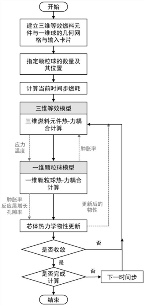
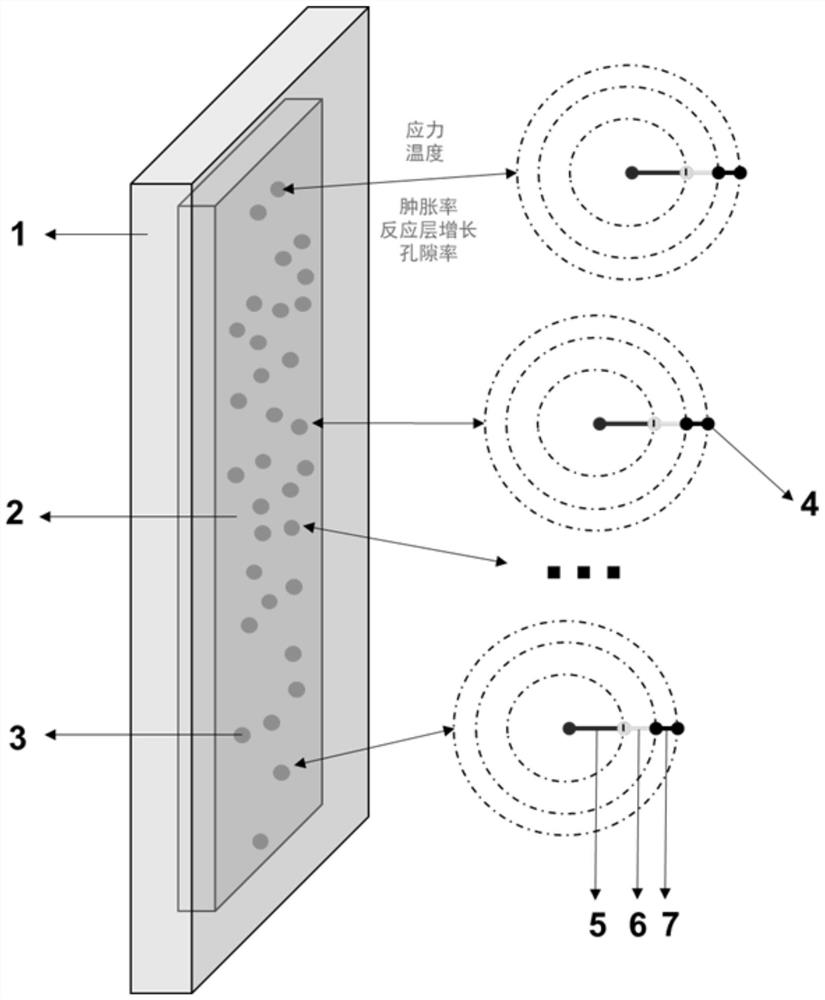
[0026] The invention provides a numerical simulation method for the multi-particle characteristics of dispersive fuel, figure 1 The flow chart of this method, figure 2 It is a schematic diagram of the coupling of the two models, in which the cladding 1 and the fuel core 2 form a three-dimensional equivalent fuel element geometric model, and the fuel particles 5, the reaction layer 6 and the matrix layer 7 form a one-dimensional particle sphere geometric model 4. The geometric model 4 of the one-dimensional particle ball can be randomly distributed at any position 3 of the geometric model of the three-dimensional equivalent fuel element. The two models are calculated independently of each other, and the coupling is realized by a certain method. The specific method is as follows:

[0027] Step 1: According to the setting of the workin...


PUM


Abstract

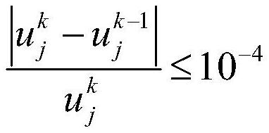
The invention discloses a numerical simulation method aiming at the multi-particle characteristic of dispersion type fuel. The method is suitable for the overall simulation of a dispersion type fuel element, considers the behaviors and influences of local particles, and comprises the following steps: 1, establishing a geometric model of a three-dimensional equivalent fuel element and a one-dimensional particle ball; 2, assigning the number and positions of one-dimensional particle balls; 3, calculating the burnup of the current time step; 4, the equivalent physical property of the three-dimensional fuel element is calculated, and heat-force coupling calculation is carried out; 5, acquiring the stress and the temperature calculated in the step 4, and taking the stress and the temperature as boundary conditions of a one-dimensional ball model to carry out heat-force coupling calculation; 6, feeding back the particle swelling rate calculated in the step 5 to the three-dimensional fuel element; 7, updating the physical property of the three-dimensional equivalent fuel element material according to the calculation result of the step 5; 8, repeating the steps 4, 5, 6 and 7 at the current time step until the convergence requirement is met; and 9, entering the next time step, and repeating the steps 3, 4, 5, 6 and 7 until all-time calculation is completed.

Description

technical field [0001] The invention belongs to the technical field of method inventions, and in particular relates to a numerical simulation method for multi-particle characteristics of dispersive fuels Background technique [0002] Dispersion fuel element is a new type of high-performance fuel element, which is a solid nuclear fuel in which fissile material is dispersed in a non-fissionable matrix in the form of small particles. Dispersion fuel element has the advantages of low fuel core temperature, small heat capacity, deep burnup, etc. It has great advantages in thermal hydraulic performance and is widely used in research reactors. [0003] Since the number of fuel particles in the dispersive fuel can reach tens of thousands, if modeling and meshing the entire fuel element and all the particles in it, it will consume huge computing resources, which is difficult to achieve. Therefore, the research on dispersive fuel elements at home and abroad is mainly carried out from...

Claims


Application Information

Patent Timeline
IPC IPC(8): G06F30/20G06F111/10G06F119/08G06F119/14
CPCG06F30/20G06F2111/10G06F2119/14G06F2119/08Y02E30/30
Inventor 秋穗正向烽瑞巫英伟贺亚男章静田文喜苏光辉
Owner XI AN JIAOTONG UNIV
Why Eureka
Eureka Blog
Learn More