
New energy automobile battery mounting structure capable of improving cruising ability

A new energy vehicle and installation structure technology, which is applied to structural parts, electric vehicles, secondary batteries, etc., can solve the problems of vehicle mileage attenuation, and achieve the goal of improving battery life, reducing power consumption, and uniform distribution of positions and quantities Effect

Pending Publication Date: 2022-08-05
江苏建康汽车有限公司
View PDF0 Cites 0 Cited by
  • Summary
  • Abstract
  • Description
  • Claims
  • Application Information

AI Technical Summary

Problems solved by technology

[0004] The purpose of the present invention is to provide a new energy vehicle battery installation structure to improve battery life, so as to solve the problem that the low temperature environment has a very significant impact on the available capacity and charge and discharge performance of the battery in the above background technology, and the low temperature attenuation characteristics of the battery cannot be avoided. The problem of important factors affecting the attenuation of vehicle cruising range

Method used


Image

  • New energy automobile battery mounting structure capable of improving cruising ability
  • New energy automobile battery mounting structure capable of improving cruising ability
  • New energy automobile battery mounting structure capable of improving cruising ability

Examples


Embodiment Construction

[0035] The technical solutions in the embodiments of the present invention will be clearly and completely described below with reference to the accompanying drawings in the embodiments of the present invention. Obviously, the described embodiments are only a part of the embodiments of the present invention, rather than all the embodiments. Based on the embodiments of the present invention, all other embodiments obtained by those of ordinary skill in the art without creative efforts shall fall within the protection scope of the present invention.

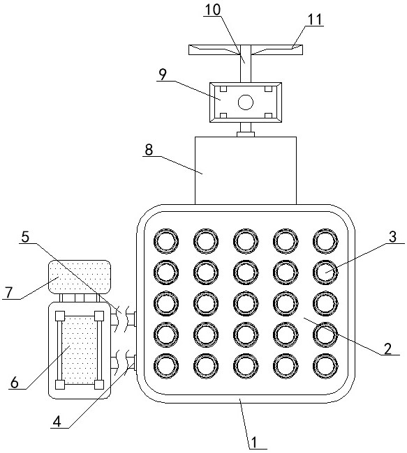
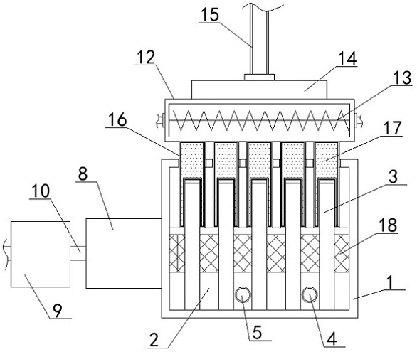
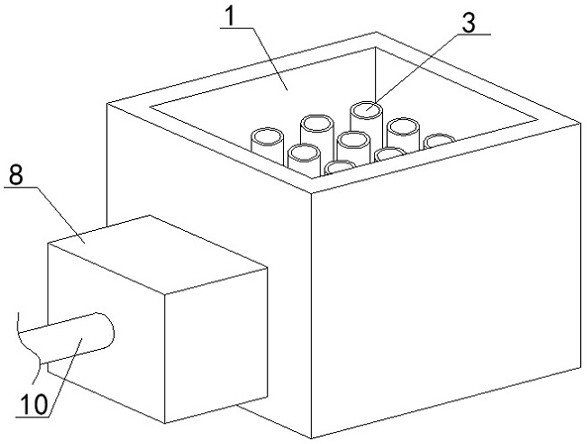
[0036] see Figure 1-7 , the present invention provides a technical solution: a new energy vehicle battery installation structure for improving battery life, comprising:

[0037]The mounting frame 1 is the main outer frame mounting structure of the equipment. The battery pack 3 is arranged inside the mounting frame 1; the cooling shell 2 is located inside the mounting frame 1. The inside of the shell 2 is respectively provided with ...


PUM


Abstract

The invention discloses a new energy automobile battery mounting structure capable of improving cruising ability, which comprises a mounting frame which is a main outer frame mounting structure of equipment, and a battery pack is arranged in the mounting frame; the cooling shell is located in the mounting frame, a honeycomb frame is arranged between the cooling shell and the mounting frame, a liquid inlet and a liquid outlet are formed in the cooling shell, one end of the liquid inlet and one end of the liquid outlet are connected with an evaporator, and the output end of the evaporator is connected with a condenser; the thermal insulation box is located on the outer surface of one end of the mounting frame, the front end of the thermal insulation box is connected with a wind driven generator, the middle end of the wind driven generator is connected with a driven shaft, and one end of the driven shaft penetrates through the wind driven generator and the thermal insulation box. According to the new energy automobile battery mounting structure capable of improving the cruising ability, the diameter of the ventilation opening is changed through rotation of the air guide plate, the transmission mode of air can be changed, and the cooling effect and the heating effect can be achieved respectively.

Description

technical field [0001] The invention relates to the technical field of new energy vehicles, in particular to a battery installation structure for new energy vehicles that improves the endurance capacity. Background technique [0002] At present, energy forms and environmental pressures on a global scale are increasingly tense. Electric vehicles have developed rapidly as a new type of vehicle with the advantages of energy saving, environmental protection, high energy conversion efficiency, and diversified energy sources. According to relevant data, in 2010, the sales volume of electric vehicles in my country was less than 10,000, only 7,200; by 2015, the annual production of electric vehicles totaled 340,400, and the sales volume reached 331,100, an increase of nearly 50 times. The battery is not only the energy source of electric vehicles, but also the technical bottleneck that limits the improvement of electric vehicles. As the heart of electric vehicles, power batteries de...

Claims


Application Information

Patent Timeline
Patent Type & Authority Applications(China)
IPC IPC(8): H01M10/613H01M10/625H01M10/643H01M10/615H01M10/6571H01M10/6563H01M10/6566H01M10/6568H01M10/6569H01M50/249H01M50/213H01M50/244
CPCH01M10/613H01M10/625H01M10/643H01M10/615H01M10/6571H01M10/6563H01M10/6566H01M10/6568H01M10/6569H01M50/249H01M50/213H01M50/244Y02T10/7072
Inventor 王雷
Owner 江苏建康汽车有限公司
Learn More