Carrier discontinuous modulation method of three-phase Vienna rectifier

A modulation method and technology of three-phase modulated waves, applied in the field of power electronics, can solve the problems of complex implementation, increase of intermediate variables and judgment conditions, and cumbersome judgment steps, etc., achieve short time required, simple judgment conditions, and reduce calculation burden Effect

Pending Publication Date: 2022-08-05
HEBEI UNIV OF TECH
View PDF0 Cites 0 Cited by
  • Summary
  • Abstract
  • Description
  • Claims
  • Application Information

AI Technical Summary

Problems solved by technology

However, this method adds additional intermediate variables and judgment conditions, making its calculation complicated
For the unbalanced midpoint voltage, the literature "X.Wu, G.Tan, G.Yao, C.Sun and G.Liu, A Hybrid PWM Strategy for Three-Level Inverter With Unbalanced DCLinks, in IEEE Journal of Emerging and Selected Topics in Power Electronics, vol.6, no.1, pp.1-15, March 2018." proposed a hybrid modulation method of SVPWM and CBPWM, which can make the T-type inverter in the state of unbalanced midpoint voltage Still works, but when this method is applied to the Vienna rectifier, the reference voltage cannot be in phase with the current at the zero crossing of the current, resulting in poor current THD performance
For load imbalance, the literature "Y.Ming et al., "A Hybrid Carrier-Based DPWM with Controllable NP Voltage for Three-Phase Vi enna Rectifiers," in IEEE Transactions on Transportation Electrification, doi:10.1109 / TTE.2021.3129778." A carrier discontinuous modulation method is proposed. By introducing different adjustment coefficients to change the effect of zero-sequence components, the problem of current zero-crossing distortion is reduced. However, this method requires complex sector judgments, and according to different sectors Area and the positive and negative of the reference voltage to determine multiple coefficients, and increase the comparison of intermediate variables, the judgment steps are more cumbersome, and the implementation is more complicated

Method used


Image

  • Carrier discontinuous modulation method of three-phase Vienna rectifier
  • Carrier discontinuous modulation method of three-phase Vienna rectifier
  • Carrier discontinuous modulation method of three-phase Vienna rectifier

Examples


Embodiment Construction

[0038] The present invention will be further described below with reference to the accompanying drawings and specific embodiments.

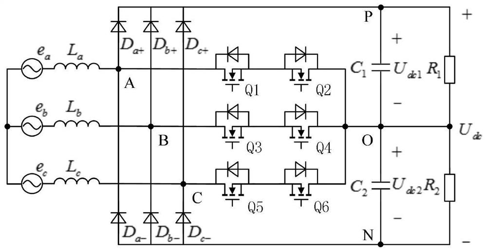
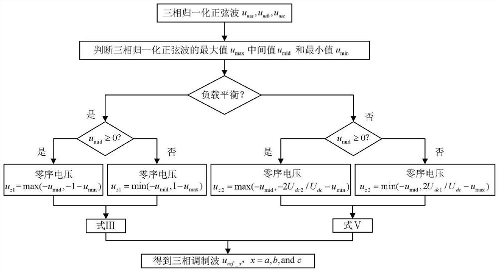
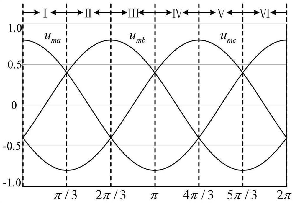
[0039] see figure 1 Fig. 7 shows a carrier discontinuous modulation method of a three-phase Vienna rectifier in the present invention.

[0040] like figure 1 As shown, the main circuit topology diagram of the present invention includes a voltage source e of phase A electricity a , B-phase voltage source e b , C-phase voltage source e c , the first to third inductors L a , L b , L c , the first to sixth diodes D a+ , D a- , D b+ , D b- , D c+ , D c- , the first to sixth switches Q 1 , Q 2 , Q 3 , Q 4 , Q 5 , Q 6 , the first capacitor C 1 , the second capacitor C 2 , the first resistor R 1 , the second resistor R 2 , the voltage source e of the A-phase electricity a , B-phase voltage source e b , C-phase voltage source e c one ends are connected together, the first inductor L a A voltage source e connected in series with p...


PUM


Abstract

The invention discloses a carrier intermittent modulation method of a three-phase Vienna rectifier. The method comprises the following steps: according to a three-phase normalization formula of an SPWM modulation strategy of the three-phase Vienna rectifier, calculating normalized sine waves of A-phase voltage, B-phase voltage and C-phase voltage as uma, umb and umc respectively; defining the maximum value of the three-phase normalized sine wave at a certain moment as umax, the intermediate value as umid and the minimum value as umin; when the load is balanced, the injected zero-sequence voltage is uz1, according to the modulation method, uz1 is made to be equal to max (-umid,-1-umin) when umid is larger than or equal to 0, and uz1 is made to be equal to min (-umid, 1-umax) when umid is smaller than 0; when the load is unbalanced, the injected zero-sequence voltage is uz2, according to the modulation method, uz2 is made to be equal to max (-umid,-2Udc2 / Udc-umin) when umid is larger than or equal to 0, and uz2 is made to be equal to min (-umid, 2Udc1 / Udc-umax) when umid is smaller than 0; and a three-phase modulation wave of the three-phase Vienna rectifier is obtained by injecting the zero-sequence voltage uz1 / uz2 into the three-phase normalized sine wave.

Description

technical field [0001] The invention relates to the field of power electronics, in particular to a carrier wave discontinuous modulation method of a three-phase Vienna rectifier. Background technique [0002] Three-phase Vienna rectifiers are suitable for high-frequency three-phase power factor correction applications due to their high efficiency, high power density and unity power factor, such as electric vehicle charging and aerospace power supplies. Aeronautical applications require converters to feature miniaturization and higher power density. High power density means that the switching frequency of the switch tube of the device needs to be increased. However, at a higher switching frequency of the switch, on the one hand, the buffer, circuit and parasitic parameters of the switching device will affect the switching transient process, resulting in poor input current waveform quality; on the other hand, it will increase the switching loss of the converter and reduce the...

Claims


Application Information

Patent Timeline
Patent Type & Authority Applications(China)
IPC IPC(8): H02M7/04H02M7/217H02M7/23H02M7/25H02M1/12
CPCH02M7/04H02M7/2173H02M7/23H02M7/25H02M1/12Y02B70/10
Inventor 汤雨裴玉硕史哲
Owner HEBEI UNIV OF TECH
Why Eureka
Try Eureka