Intelligent warehouse logistics screening, distributing, feeding and conveying device

A transmission device and warehouse technology, applied in the field of logistics, can solve the problems of reducing scanning efficiency, reducing screening efficiency, reducing feeding efficiency, etc., and achieve the effect of simplifying the scanning process, improving the screening efficiency, and improving the feeding efficiency.

Pending Publication Date: 2022-08-09
北京华科众合科技有限公司
View PDF0 Cites 0 Cited by
  • Summary
  • Abstract
  • Description
  • Claims
  • Application Information

AI Technical Summary

Problems solved by technology

[0002] Smart warehouse logistics refers to relying on technologies such as the Internet of Things, artificial intelligence, big data, and cloud computing to create intelligent full-scale operations in the factory from procurement, picking, production, warehousing, delivery, and after-sales. , production, warehousing to delivery and other operation links, to realize the "four modernizations" management of internal warehousing and logistics in the enterprise, which is mobile, transparent, lean and intelligent, and it is necessary to allocate feeding and conveying devices during logistics screening; but the existing distribution When feeding, the feeding and conveying device needs to be manually fed, which increases the complexity of feeding, thereby reducing the feeding efficiency and increasing the labor burden, and it does not have a material limit structure, which makes it impossible for objects to be moved every time. Each item is fed separately, which leads to faster feeding, which leads to inconvenient screening, which reduces the screening efficiency, and when multiple single items are conveyed, manual scanning is required, which reduces the scanning efficiency.

Method used


Image

  • Intelligent warehouse logistics screening, distributing, feeding and conveying device
  • Intelligent warehouse logistics screening, distributing, feeding and conveying device
  • Intelligent warehouse logistics screening, distributing, feeding and conveying device

Examples


Embodiment 1

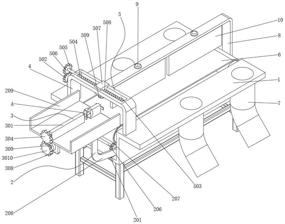
[0025] See figure 1 and image 3 , A smart warehouse logistics screening allocation and distribution of feeding transmission devices, including conveyor rack main body 1. feed component 2. Material limit component 3, first frame 4, and mobile scanning component 5, on one side of the side wall of the main body of the conveyor rack 1, there are fixed fixation on the outer wall of the main body of the main body of the conveyor frame 1. Input component 2, the material limit component 3 on the outer wall of the main body 1 of the conveyor rack main body 1, the welding on the top of the top of the conveyor rack main body 1 has the first frame 4, and the mobile scanning component on the top of the first frame 4 on the inner wall of the first frame 4 5; The conveyor mechanism 6 is installed on the inner wall of the main body 1 of the conveyor rack, which allows the first object to slip to the conveyor 6 to facilitate the transportation of the object and improve the conveying effect. There ...

Embodiment 2

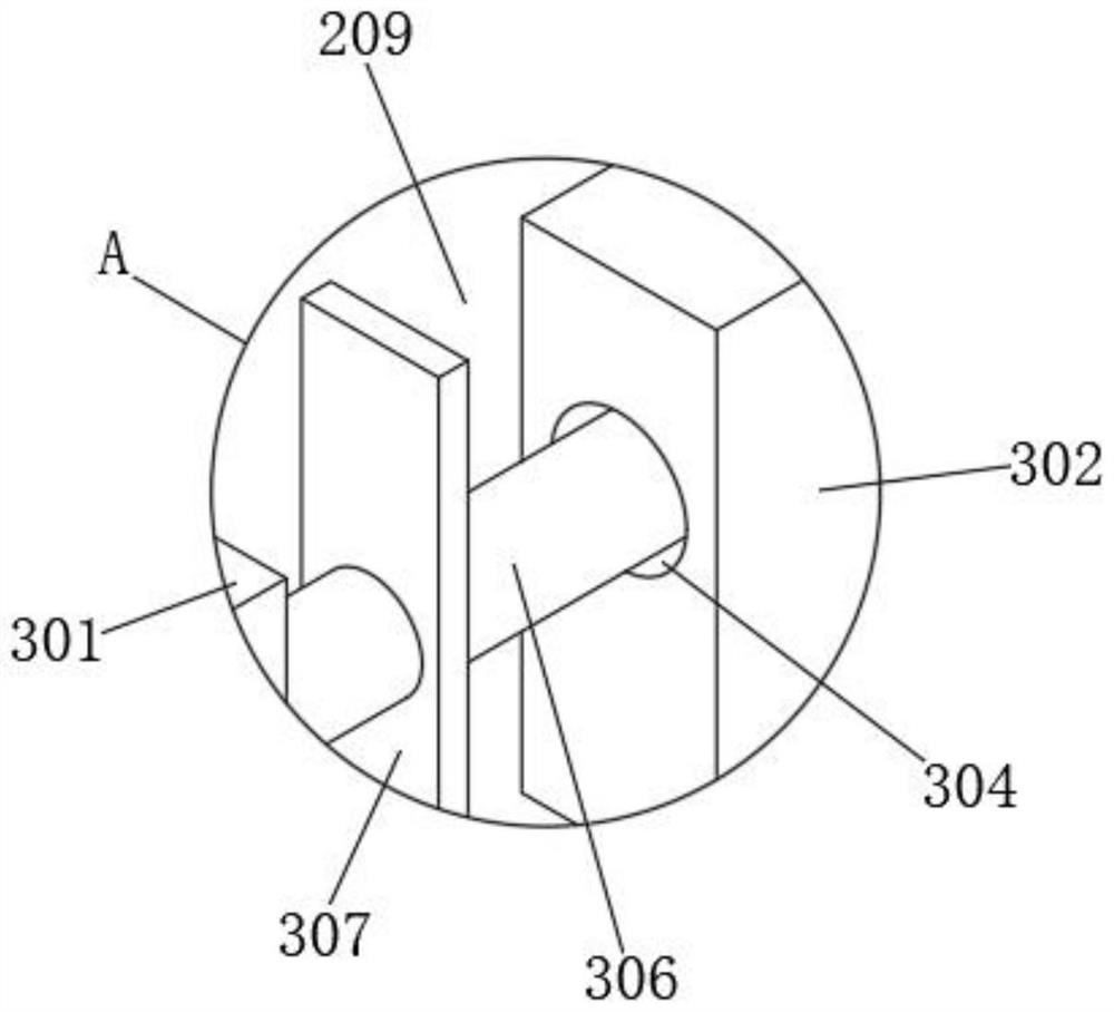
[0029] See figure 2 and Figure 4, Material Limited Components 3 include the first isolation board 301, the second isolation board 302, the first rotor 303, the third gear 304, the second rotor 305, the first limit baffle 306, the second limit baffle 307 307 , Vertical board 308, third motor 309, and fourth gear 3010, the welding of the top wall of the feed board 209 has the first isolation board 301, the feed board 209 is located on the inner wall on the inner wall of the first isolated board. The outer wall of the first isolation board 301 is installed with a third gear 304 on the outer wall of the first isolation board 301. The corresponding second rotor 305 on the inner wall of the side has the first rotor 303, and the second rotor 305 is located on the outer wall between the first isolation board 301 and the second isolation board 302. The welding on the outer wall of the one end of the turning axis 305 has a second limit baffle 307, the bottom outer wall of the third gear 304...

Embodiment 3

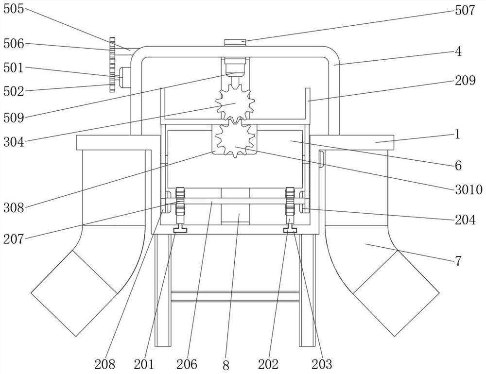
[0032] See Figure 5 , Mobile scanning components 5 include the fourth motor 501, fifth gear 502, second slide 503, second rotor pores 504, thread 505, sixth gear 506, second sliding block 507, thread hole 508 and scan camera 509 On the inner wall of the first frame 4, there is a second slide 503, and the inner wall of one side of the second slide 503 is rotated on the inner wall of the thread 505, and the corresponding threaded pole 505 on the inner wall of the second slide 503 There is a sixth gear 504 with a second -rotating hole 504 and a thread 505 on the outer wall of the ends of the thread 505. The corresponding threaded pole 505 is opened with threaded holes 508, and the bottom end wall of the second slide 507 is installed with a scan camera 509, the bottom outer wall of the bottom end of the sixth gear 506 is installed with fifth gear 502, the first frame 4 On the inner wall of one side, a fourth motor 501 is installed, and the output shaft of the fourth motor 501 is fixed...


PUM


Abstract

The invention discloses an intelligent warehouse logistics screening, distributing, feeding and conveying device which comprises a conveying frame body, a feeding assembly, a material limiting assembly, a first support and a movable scanning assembly, the feeding assembly is fixed to the outer wall of one side of the conveying frame body, and the material limiting assembly is fixed to the outer wall of one side of the conveying frame body; a first support is welded to the outer wall of the top end of the conveying frame body, and a movable scanning assembly is fixed to the inner wall of the top end of the first support. The feeding assembly comprises a first sliding groove, a rack, a first sliding block, a second motor, a first gear and a first rotating shaft. According to the automatic feeding device, objects can be automatically fed, so that the feeding process is simplified, the feeding efficiency is improved, and the labor burden is reduced; and the single pieces to be discharged can be isolated, so that the materials can be fed at intervals, enough time can be reserved for automatic screening, the objects can reach the designated position, and the screening efficiency is improved.

Description

Technical field [0001] The invention involves the field of logistics technology and especially involves a smart warehouse logistics screening and distribution of feeding transmission devices. Background technique [0002] Intelligent warehouse logistics refers to relying on the Internet of Things, artificial intelligence, big data, cloud computing and other technologies to create a full operation link from intelligent plants such as procurement, receipt, production, warehousing to delivery and after -sales. , Production, warehousing to delivery and other operation links to realize the "four -way" management of the internal warehousing logistics and logistics of the enterprise's internal storage and logistics, which are allocated during logistics screening. When the feed transmission device is made of feeding, it needs to be manually feed, which increases the complexity of the feed, thereby reducing the feeding efficiency and increasing the manual burden. The separation of the met...

Claims


Application Information

Patent Timeline
Patent Type & Authority Applications(China)
IPC IPC(8): B65G1/04B65G11/02B07C5/34B07C5/36
CPCB65G1/04B65G11/023B07C5/34B07C5/36
Inventor 王奕标薛婷
Owner 北京华科众合科技有限公司
Why Eureka
Try Eureka