
Device and method for dynamically adjusting angle of feet-lock anchor pipe in tunnel

A technology of dynamic adjustment and locking foot anchor pipe, which is applied in the direction of drill pipe, casing, earthwork drilling and mining, etc., can solve the problems such as large error of workers' drilling angle, inability to dynamically adjust, and inability to meet the advanced concept of tunnel dynamic management, etc., to achieve The effect of improving the qualified rate of welds, convenient dynamic management and simple structure

Active Publication Date: 2022-08-09
CHINA RAILWAY NO 9 GRP NO 7 ENG CO LTD +1
View PDF6 Cites 1 Cited by
  • Summary
  • Abstract
  • Description
  • Claims
  • Application Information

AI Technical Summary

Problems solved by technology

At present, the lock foot anchor pipe is mainly drilled by hand-held rock drills, and the angle is generally 30~50°, which is usually manually drilled. Because the position of each drilling hole is different, the angle error of the worker's drilling angle is large, and the monitoring and measurement results cannot be used. Dynamic adjustment cannot meet the advanced concept of tunnel dynamic management

Method used


Image

  • Device and method for dynamically adjusting angle of feet-lock anchor pipe in tunnel
  • Device and method for dynamically adjusting angle of feet-lock anchor pipe in tunnel
  • Device and method for dynamically adjusting angle of feet-lock anchor pipe in tunnel

Examples


Embodiment Construction

[0032] The technical solutions in the embodiments of the present invention will be clearly and completely described below. Obviously, the described embodiments are only a part of the embodiments of the present invention, rather than all the embodiments. Based on the embodiments in the present invention, all other embodiments obtained by those of ordinary skill in the art fall within the protection scope of the present invention.

[0033] In the description of the present invention, the terms "portrait", "horizontal", "upper", "lower", "front", "rear", "left", "right", "vertical", "horizontal", " The orientations or positional relationships indicated by "top" and "bottom" are based on the orientations or positional relationships shown in the accompanying drawings, and are only for the convenience of describing the present invention rather than requiring the present invention to be constructed and operated in a specific orientation, and therefore cannot be understood as Limitati...


PUM


Abstract

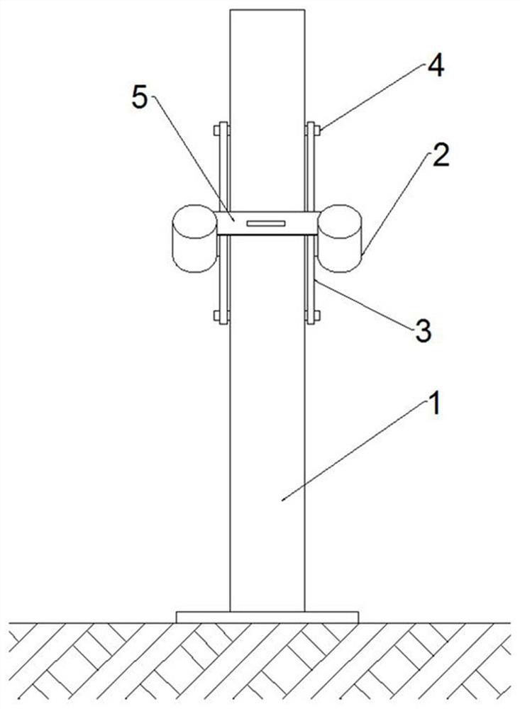
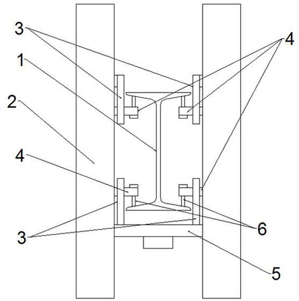
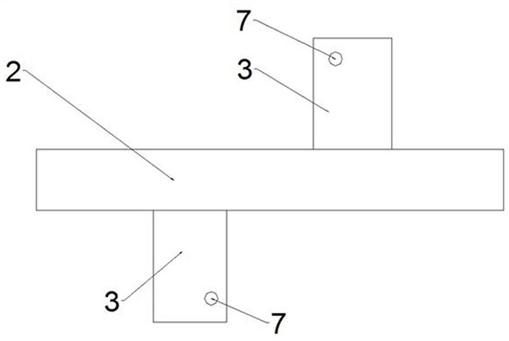
The invention relates to the technical field of tunnel feet-lock anchor pipe installation, in particular to a dynamic adjusting device and method for the angle of a feet-lock anchor pipe in a tunnel, and the dynamic adjusting device comprises two guide pipes which are used for guiding a drill bit; the two ends of the pushing piece are correspondingly connected to the two guide pipes respectively; the two fixing plate sets are arranged between the two guide pipes; the shaft pin is detachably connected to the fixing plate and correspondingly extends into the abdominal cavity of the arch foot I-shaped steel; and the fixing bolts are arranged at the ends, extending into the abdominal cavity of the arch foot I-shaped steel, of the shaft pins and abut against the inner side of the flange of the arch foot I-shaped steel so as to fix the guide pipes. The adjusting device is simple in structure, all materials are common materials in building construction, it can be guaranteed that the angle error of the tunnel feet-lock anchor pipe is within 5 degrees through the adjusting device, the qualification rate of weld joints of feet-lock connecting ribs is greatly increased, and the production efficiency is improved. And meanwhile, the problems that the angle error is large and the lock foot connecting rib is difficult to weld due to original manual drilling are solved.

Description

technical field [0001] The invention belongs to the technical field of tunnel foot-locking anchor pipe installation, and in particular relates to a device and method for dynamically adjusting the angle of a foot-locking anchor pipe in a tunnel. Background technique [0002] In the field of tunnel construction, the locking foot anchor pipe is an important part of the initial support. When the arch foot is exposed in the construction of the step method or the guide pit method, the locking foot anchor pipe plays a very strong role in limiting settlement and convergence. The foot-locking anchor pipe is generally installed on both sides of the profiled steel arch, close to the flange plate of the steel frame, and is installed and grouted by a hand-held rock drill or bolt machine. The monitoring and measurement data can have various parameters, but generally the downward depression angle is mainly used to resist the vertical and horizontal in-situ stress of the surrounding rock it...

Claims


Application Information

Patent Timeline
Patent Type & Authority Applications(China)
IPC IPC(8): E21D20/00E21B19/24
CPCE21D20/003E21B19/24Y02E10/20
Inventor 吴佳骏陈向利李振兵权循亮王焕民彭红岩侯经宇郑玉强赵一山尚祺栋张明杰陈岩
Owner CHINA RAILWAY NO 9 GRP NO 7 ENG CO LTD
Learn More