
Clock correction method, clock data recovery circuit, chip, receiving end and terminal

A clock data recovery and clock correction technology, applied in the direction of electrical components, automatic power control, etc., can solve the problems of occupation, large circuit area and power consumption, and achieve the effect of improving accuracy, low power consumption, and simple calculation logic

Pending Publication Date: 2022-08-09
AMOLOGIC (SHANGHAI) CO LTD
View PDF0 Cites 0 Cited by
  • Summary
  • Abstract
  • Description
  • Claims
  • Application Information

AI Technical Summary

Problems solved by technology

[0008] However, this method requires an analog circuit to implement the above-mentioned relatively complex logic calculation, which will occupy a large circuit area and power consumption

Method used


Image

  • Clock correction method, clock data recovery circuit, chip, receiving end and terminal
  • Clock correction method, clock data recovery circuit, chip, receiving end and terminal
  • Clock correction method, clock data recovery circuit, chip, receiving end and terminal

Examples


Embodiment Construction

[0038] In order to make the objectives, technical solutions and advantages of the present disclosure clearer, the present disclosure will be further described in detail below with reference to the specific embodiments and the accompanying drawings.

[0039] It should be noted that, unless otherwise defined, the technical or scientific terms used in one or more embodiments of the present specification shall have the usual meanings understood by those with ordinary skill in the art to which this disclosure belongs. The terms "first," "second," and similar terms used in one or more embodiments of this specification do not denote any order, quantity, or importance, but are merely used to distinguish the various components. "Comprises" or "comprising" and similar words mean that the elements or things appearing before the word encompass the elements or things recited after the word and their equivalents, but do not exclude other elements or things. Words like "connected," "coupled,...


PUM


Abstract

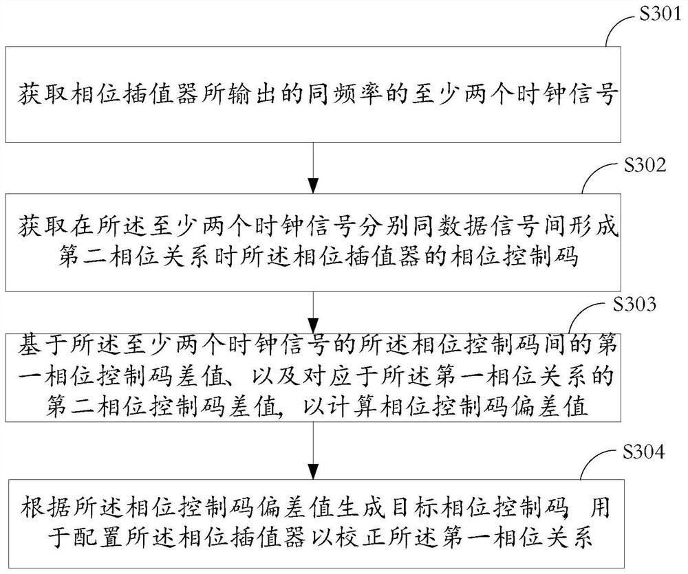
The invention discloses a clock correction method, a clock data recovery circuit, a chip, a receiving end and a terminal. The method comprises the following steps: acquiring at least two clock signals with the same frequency output by a phase interpolator; wherein the phase interpolator is configured to maintain a first phase relationship between the at least two clock signals; acquiring a phase control code of the phase interpolator when a second phase relationship is formed between the at least two clock signals and a data signal; calculating a phase control code deviation value based on a first phase control code difference value between the phase control codes of the at least two clock signals and a second phase control code difference value corresponding to the first phase relationship; and generating a target phase control code according to the phase control code deviation value, wherein the target phase control code is used for configuring the phase interpolator to correct the first phase relation. According to the scheme of the embodiment of the invention, high accuracy of data recovery of the CDR circuit is realized, the occupied circuit area is small, and the precision is high.

Description

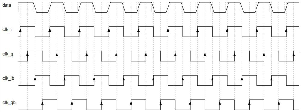
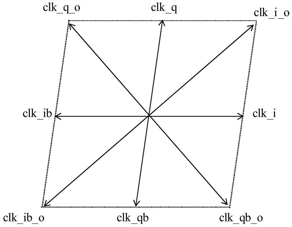
technical field [0001] One or more embodiments of this specification relate to the technical field of circuit manufacturing, and in particular, to a clock correction method, a clock data recovery circuit, a chip, a receiving end, and a terminal. Background technique [0002] The clock data recovery circuit (Clock Data Recovery CDR) is widely used in various high-speed serial communication scenarios, such as optical communication, board-level, chip-level high-speed signal transmission and so on. Its purpose is to recover the clock signal synchronized with the received data signal. [0003] Common types of clock data recovery circuits (CDR) are, for example, based on phase locked loop (PLL), delay locked loop (DLL) or phase interpolator (PI) implementations. like figure 1 As shown, taking the four-phase half-speed sampling CDR based on PI as an example, the four-way clock signals clk_i, clk_q, clk_ib, clk_qb are used to sample and restore the input data, and the clock freque...

Claims


Application Information

Patent Timeline
Patent Type & Authority Applications(China)
IPC IPC(8): H03L7/08H03L7/093
CPCH03L7/08H03L7/093
Inventor 钟威许洁皓程达
Owner AMOLOGIC (SHANGHAI) CO LTD
Learn More