Photovoltaic electric generation system of automatically tracking sun
A photovoltaic power generation system and automatic tracking technology, which is applied in the field of solar energy utilization, can solve the problems of low cost performance, poor wind resistance, and low tracking accuracy, achieve reliable and high-precision tracking, enhance wind resistance, and improve performance and price than the effect
- Summary
- Abstract
- Description
- Claims
- Application Information
AI Technical Summary
Problems solved by technology
Method used
Image
Examples
Embodiment 1
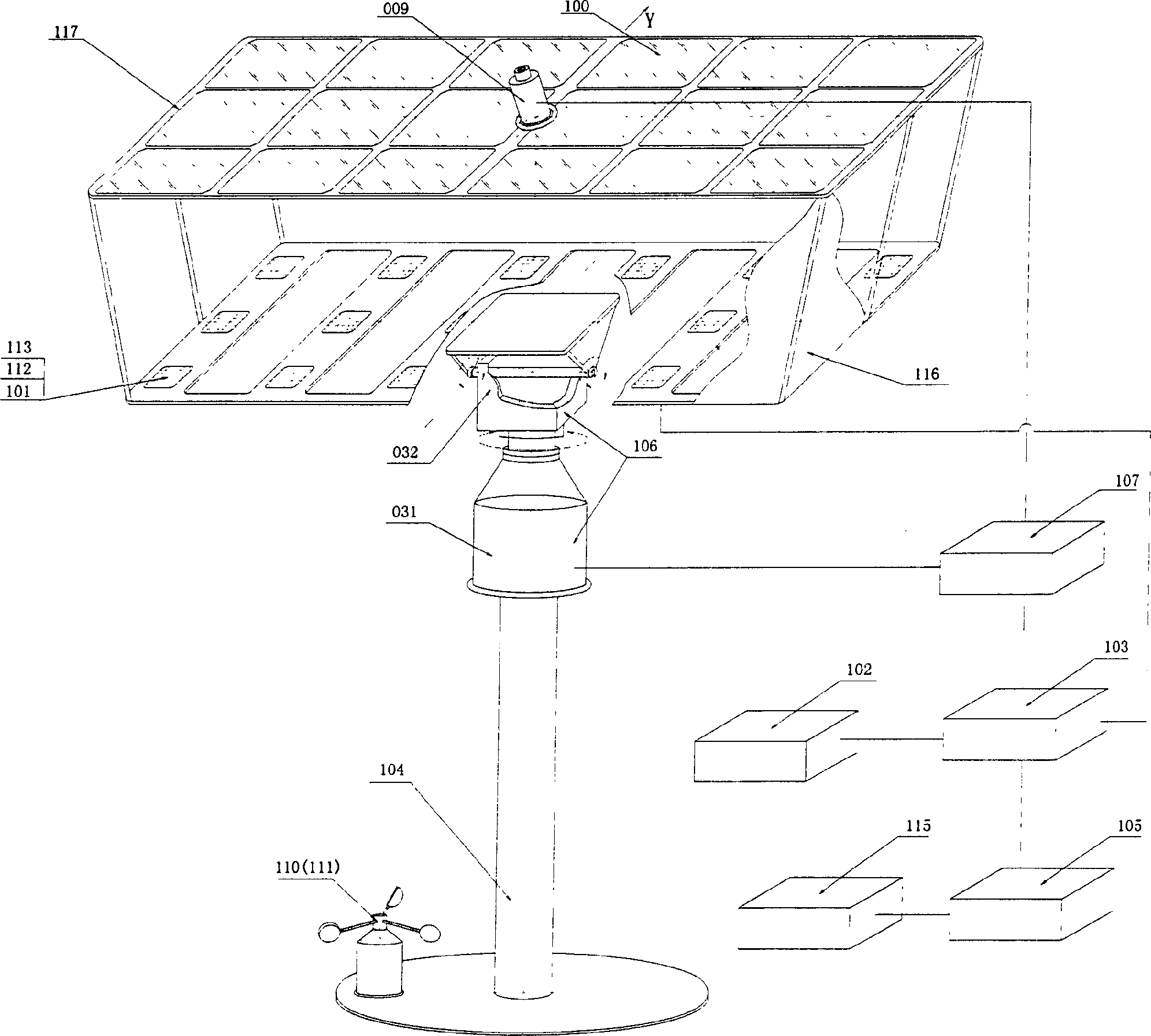
[0026] The system structure of Embodiment 1 of the present invention is as follows figure 1 As shown, the photovoltaic power generation system that automatically tracks the sun is composed of a condenser lens array 100, a solar cell array 101 and its mounting frame 117, a storage battery 102, a charge and discharge controller 103, an electrical appliance 115, a support 104, an inverter 105, and a drive The solar cell array tracks and aligns the mechanical transmission mechanism 106 of the sun, the tracking control circuit 107 that controls the mechanical transmission mechanism, the sunlight orientation sensor 009 that transmits signals to the tracking control circuit, and the radiator 109 (see Image 6 ), a dust cover 116 and a windproof reset control device 110 are composed. Both the solar battery array 101 and the condenser lens array 100 are fixed on the mounting frame 117 . The mechanical transmission mechanism 106 is composed of an azimuth (east-west direction) drive mec...
Embodiment 2
[0035] The basic structure and working principle of this embodiment are the same as those of the first embodiment, and the main difference lies in the altitude angle driving mechanism and the windproof reset control device.
[0036] like Figure 7 As shown, the mounting frame 117 is connected with the elevation angle driving mechanism 032 through the bearing 035, and the bearing 035 divides the mounting frame 117 into two parts 118 and 119 with different areas and weights, wherein the area and weight of 118 are larger than those of 119 . The altitude angle driving mechanism 032 includes an output shaft 036, a reel 037, a steel cable 038 and a fixed pulley 039, the reel 037 is fixedly connected with the output shaft 036, the fixed pulley 039 shaft is fixedly connected with the altitude angle drive 032, and the steel cable 038 It is wound on the reel 037 and connected to the installation frame 117 through the windproof reset control device 110 and the fixed pulley 039.
[0037...
Embodiment 3
[0039] This example Figure 9 As shown, the structure of Embodiment 1 is also basically the same, and its difference has two points:
[0040] One is to use ordinary solar cell components instead of concentrating lenses and concentrating solar cells, such as Figure 9 shown. In addition, a layer of toughened protective glass 114 is covered on the surface of the solar cell array.
[0041] The second is that the optical signal receiver of the sunlight orientation sensor uses a photosensitive element instead of an optical fiber. like Figure 10 As shown, both the fine-tuning optical signal receiver and the coarse-tuning optical signal detector are composed of photovoltaic cells with better parameter symmetry performance.
PUM
 Abstract
Description
Claims
Application Information
 - R&D
- Intellectual Property
- Life Sciences
- Materials
- Tech Scout
- Unparalleled Data Quality
- Higher Quality Content
- 60% Fewer Hallucinations
Browse by: Latest US Patents, China's latest patents, Technical Efficacy Thesaurus, Application Domain, Technology Topic, Popular Technical Reports.
© 2025 PatSnap. All rights reserved.Legal|Privacy policy|Modern Slavery Act Transparency Statement|Sitemap|About US| Contact US: help@patsnap.com


