
Amplifier

A technology of amplifiers and operational amplifiers, applied in amplifiers, low-frequency amplifiers, push-pull amplifiers, etc., can solve problems such as power supply voltage limitations, difficulty in temperature compensation of P-channel MOS transistors, N-channel MOS transistors Tr2, and deterioration of high-frequency characteristics

Inactive Publication Date: 2004-09-15
NIPPON PRECISION CIRCUITS
View PDF0 Cites 0 Cited by
  • Summary
  • Abstract
  • Description
  • Claims
  • Application Information

AI Technical Summary

Problems solved by technology

In addition, when it is desired to achieve low-impedance driving of the gates of the P-channel MOS transistor Tr1 and the N-channel MOS transistor Tr2, a load is applied to the OP amplifier 1, and when it is desired to reduce the load on the OP amplifier 1, the gate capacitance and the resistor The formed RC circuit produces low-pass filter operation and deteriorates high-frequency characteristics
Additionally, for Figure 23 The desired idle currents II1 and II2 are provided by the drain currents Id1 and Id2 as shown, and the supply voltage is also limited
In addition, the temperature compensation of the P-channel MOS transistor Tr1 and the N-channel MOS transistor Tr2 is also very difficult.

Method used


Image

  • Amplifier
  • Amplifier
  • Amplifier

Examples


Embodiment Construction

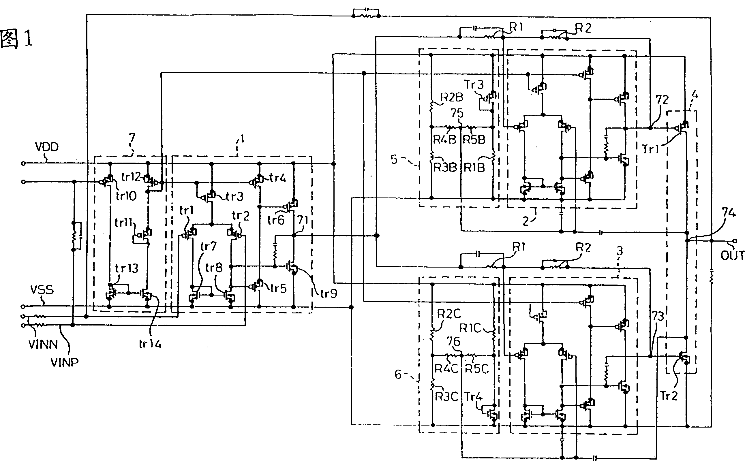
[0042] A detailed explanation of the operational amplifier according to the present invention according to the embodiment shown in FIG. 1 will be given below. First, an explanation will be given of the structure of this example. In the drawings, first, second, and third operational amplifiers (hereinafter referred to as OP amplifiers) 1, 2, and 3 are well-known operational amplifiers composed of P-channel MOS transistors tr1 to tr6 and N-channel MOS transistors tr7 to tr9. In the amplifier, the P-channel MOS transistor tr1 forms a negative-phase input terminal, and the P-channel MOS transistor tr2 forms a positive-phase input terminal, which is used to connect the connection point of the P-channel MOS transistor tr6 and the N-channel MOS transistor tr9 to form an output end. According to the OP amplifier 1, its positive input terminal VINP is biased to an intermediate potential between the positive power supply terminal VDD and the negative power supply terminal VSS, and its ...


PUM


Abstract

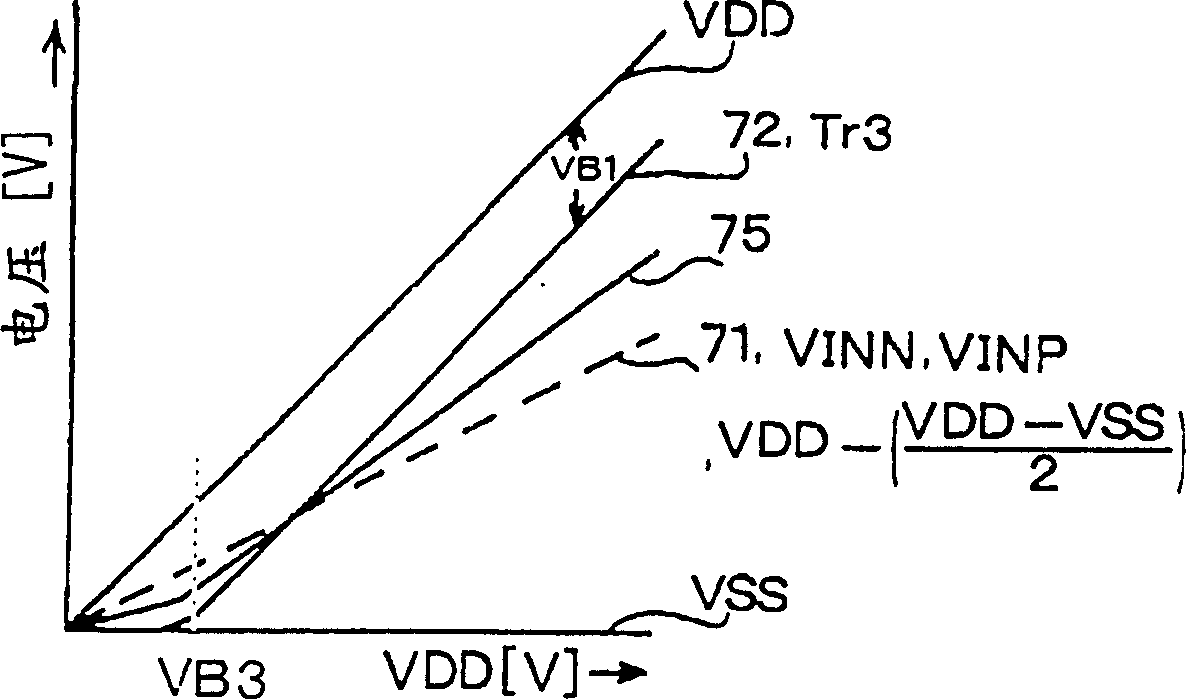
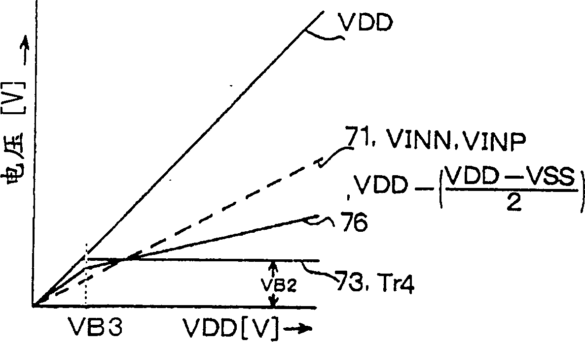
The present invention provided an amplifier, wherein voltage values provided to positive phase input terminals of a second and a third amplifier 2 and 3 are made to correspond to voltages between sources and drains of a second P-channel MOS transistor Tr3 and a second N-channel MOS transistor Tr4, a first P-channel MOS transistor Tr1 and a first N-channel MOS transistor Tr2 constituting a power buffer 4, are driven by an output signal of a first operational amplifier 1 via the second and the third amplifiers 2 and 3 and therefore, there can be provided idling currents independently from power source voltage from low power source voltage, there can be provided an output signal having small crossover distortion in a wide power source voltage range and temperature dependency thereof can be improved.

Description

technical field [0001] The present invention relates to an operational amplifier with a large output current, and more particularly to an amplifier for driving headphones, an amplifier for driving speakers used in audio equipment, and an amplifier suitable for driving other heavy loads. Background technique [0002] In the related art, according to amplifiers for supplying large output currents, such as Figure 17 , Figure 18 and Figure 19 Indicates the circuit structure. In the drawings, for convenience, the same constituent elements are denoted by the same symbols. according to Figure 17 In the shown circuit structure, the power buffer is formed by connecting the sources of the P-channel MOS transistor Tr1 and the N-channel MOS transistor Tr2 and providing an output terminal OUT, and the drain of Tr1 is connected to the negative power supply terminal VSS (for example, 0V ), the drain of Tr2 is connected to the positive power supply terminal VDD (for example, 5V), the...

Claims


Application Information

Patent Timeline
Patent Type & Authority Patents(China)
IPC IPC(8): H03F1/30H03F1/32H03F3/185H03F3/30
CPCH03F2203/45398H03F2203/45508H03F3/303
Inventor 渡边伸一
Owner NIPPON PRECISION CIRCUITS
Learn More