D.C. brushless electric motor driving equipment and air conditioner using said equipment

A brushless motor, driving equipment technology, applied in the direction of electronic commutation motor control, single motor speed/torque control, electrical components, etc., can solve the problem that the main filter cannot sufficiently eliminate noise or other similar signals, triangular signal phase Performance fluctuations, signal time delays, etc.

Inactive Publication Date: 2004-12-29
HITACHI JOHNSON CONTROLS AIR CONDITIONING INC
View PDF0 Cites 0 Cited by
  • Summary
  • Abstract
  • Description
  • Claims
  • Application Information

AI Technical Summary

Problems solved by technology

Also, noise or other similar signals, which have a higher frequency than the fundamental frequency of these spike waveforms and induced voltages, cannot be adequately removed by the main filter, and it is impossible to accurately assume or obtain a triangular signal if its waveform is not smooth The relative position between the rotor and stator windings, so at the output stage of the aforementioned comparator that compares the triangular signal and the reference signal, a low-pass filter is additionally added to eliminate high-frequency signals such as noise or other similar signals
[0008] However, in order to smooth the waveform of the triangular signal, it is sufficient to make the time constant of the filter large, but this causes a time delay of the signal, so the time constant setting of the filter has an upper limit
In addition, in the DC brushless motor, the waveform of the peak voltage changes according to the load of the motor, but the time constant setting of the filter has an upper limit, so there is a problem that the phase of the triangular signal fluctuates due to the waveform change of the triangular signal , so it is impossible to keep the phase difference between the induced voltage and the triangular signal at 90°
[0009] In this way, when the filter is used to assume or obtain the relative position between the rotor and the stator winding, due to the limitation of frequency characteristics and filter time constant setting, especially when driving a DC brushless motor under a wide range of revolutions, or when When operating a DC brushless motor under a wide range of load conditions, it causes a decrease in accuracy in assuming the relative relationship between the rotor and stator windings, making it difficult to drive a DC brushless motor with good efficiency under stable conditions

Method used


Image

  • D.C. brushless electric motor driving equipment and air conditioner using said equipment
  • D.C. brushless electric motor driving equipment and air conditioner using said equipment
  • D.C. brushless electric motor driving equipment and air conditioner using said equipment

Examples


Embodiment Construction

[0024] Hereinafter, embodiments according to the present invention will be fully explained with reference to the accompanying drawings.

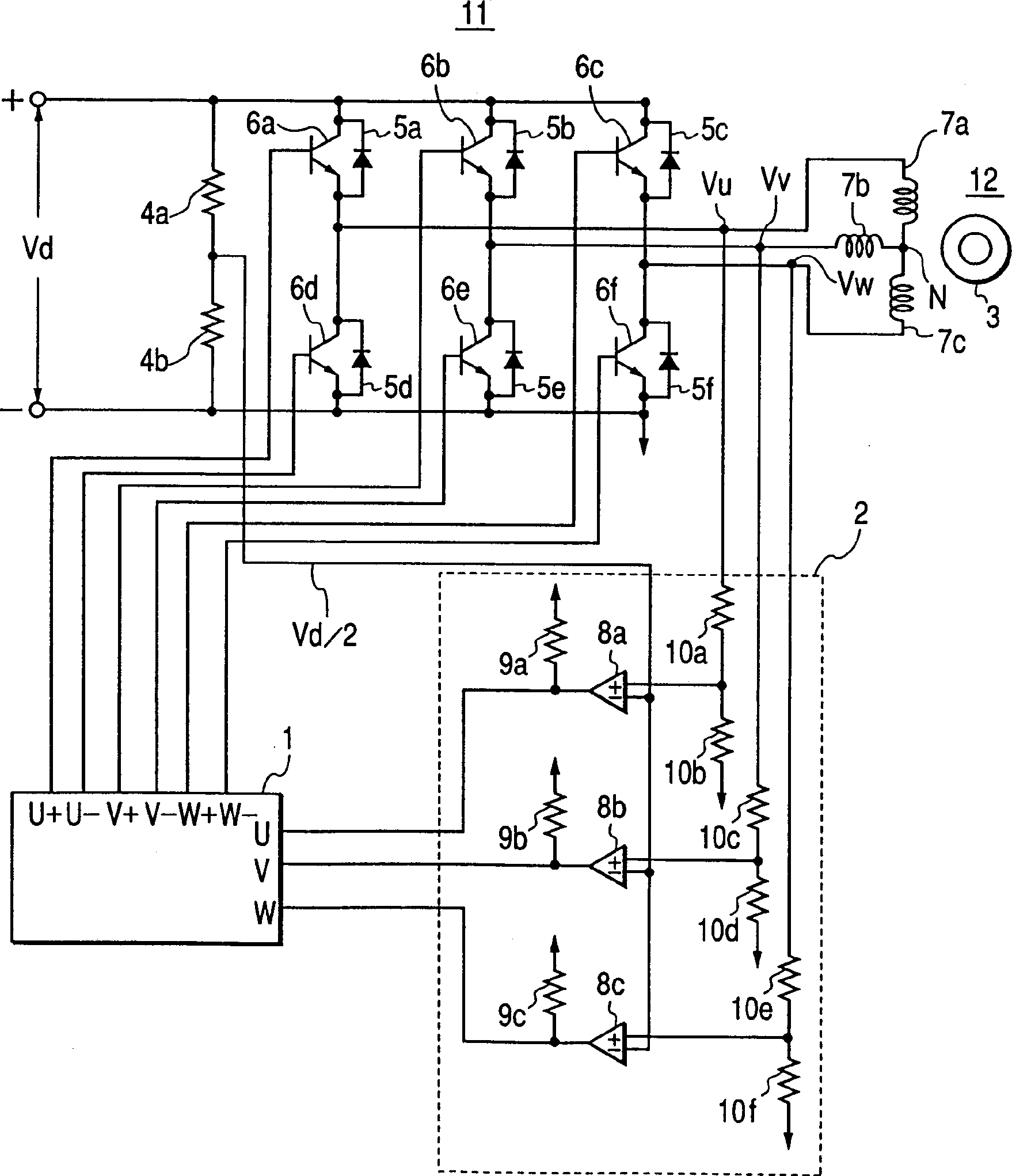
[0025] figure 1 A circuit diagram showing a first embodiment of a direct current (DC) brushless motor driving apparatus according to the present invention, wherein reference numeral 1 denotes a microcomputer, reference numeral 2 denotes a rotor magnetic pole position detecting circuit, reference numeral 3 denotes a rotor, and reference numerals 4a and 4b denote Reference voltage detection resistors, reference numerals 5a-5f represent freewheeling or freewheeling diodes, numerals 6a-6f represent semiconductor switching elements, numerals 7a-7c represent stator windings, numerals 8a-8c represent comparators, and numerals 9a-9c represent load resistors The reference numerals 10a-10f denote detection resistors for motor terminal voltage, the reference numeral 11 denotes an inverter, and the reference numeral 12 denotes a DC brushless motor.

[...


PUM


Abstract

The purpose of the invention is to detect the communication timings of an inverter securely when a DC brushless motor is started and the load of the motor is light. The microcomputer 1 of a DC brushless motor drive generates inverter drive signals U+,..., W-. The switching devices 6a to 6f of an inverter 11 are driven with the PWM signals of the drive signals for every current application section in a predetermined order to supply a drive current to a DC brushless motor 12 to rotate. The level of a pole position detection signal is detected in accordance with the PWM signals to detect the switching timing (communication timing) of the current application section.

Description

technical field [0001] The present invention relates to a DC brushless motor driving device in which an inverter is used, and more particularly, the present invention relates to a DC brushless motor driving device, and an air conditioner using the same, in which The speed induced between the terminals is proportional to the electromotive force, and the relative position (hereinafter, referred to as "magnetic pole position") between the armature winding (rotor winding) and the stator winding is detected to control the number of revolutions thereof. Background technique [0002] For example, in Japanese Patent Publication No. Sho 59-36519 (1984), a conventional example of a DC brushless motor driving device is described in which by detecting the magnetic pole position of the rotor, that is, due to the The speed induced between the terminals is proportional to the relative position between the magnetic rotor (hereinafter, simply referred to as "rotor") and the stator winding ca...

Claims


Application Information

Patent Timeline
Patent Type & Authority Patents(China)
IPC IPC(8): H02P6/06H02P6/08H02P6/18H02P6/182
CPCH02P6/20H02P6/085H02P6/185
Inventor 和久井豊光加藤浩二奥山敦寺内英樹牧田稔金子喜作岩崎真之田村建司
Owner HITACHI JOHNSON CONTROLS AIR CONDITIONING INC
Why Eureka
Try Eureka