
Improved multimode optical fiber and its prepn. method

A technology of multimode optical fiber and manufacturing method, applied in the field of multimode optical fiber and its manufacturing, can solve problems such as affecting the bandwidth characteristics of optical fiber, reducing optical fiber performance, affecting the application of multimode optical fiber, etc., to increase bandwidth, reduce inter-mode delay, eliminate The effect of the depression in the center

Inactive Publication Date: 2005-04-20
SICHUAN LEFEI OPTOELECTRONICS TECH CO LTD
View PDF4 Cites 2 Cited by
  • Summary
  • Abstract
  • Description
  • Claims
  • Application Information

AI Technical Summary

Problems solved by technology

[0015] The technical problem to be solved by the present invention is: aiming at the existing multimode optical fiber having center depression and large mode delay, thereby affecting the bandwidth characteristics of the optical fiber, reducing the performance of the optical fiber, and causing problems affecting the application of the multimode optical fiber in high-speed networks, it is proposed An improved multimode optical fiber and its manufacturing method to make up for the deficiencies of existing products

Method used


Image

  • Improved multimode optical fiber and its prepn. method
  • Improved multimode optical fiber and its prepn. method
  • Improved multimode optical fiber and its prepn. method

Examples


Embodiment Construction

[0033] The present invention will be further described below in conjunction with accompanying drawing:

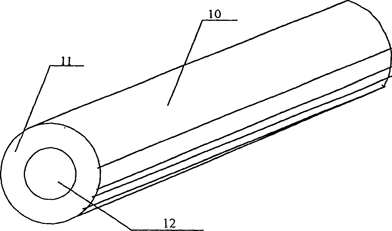
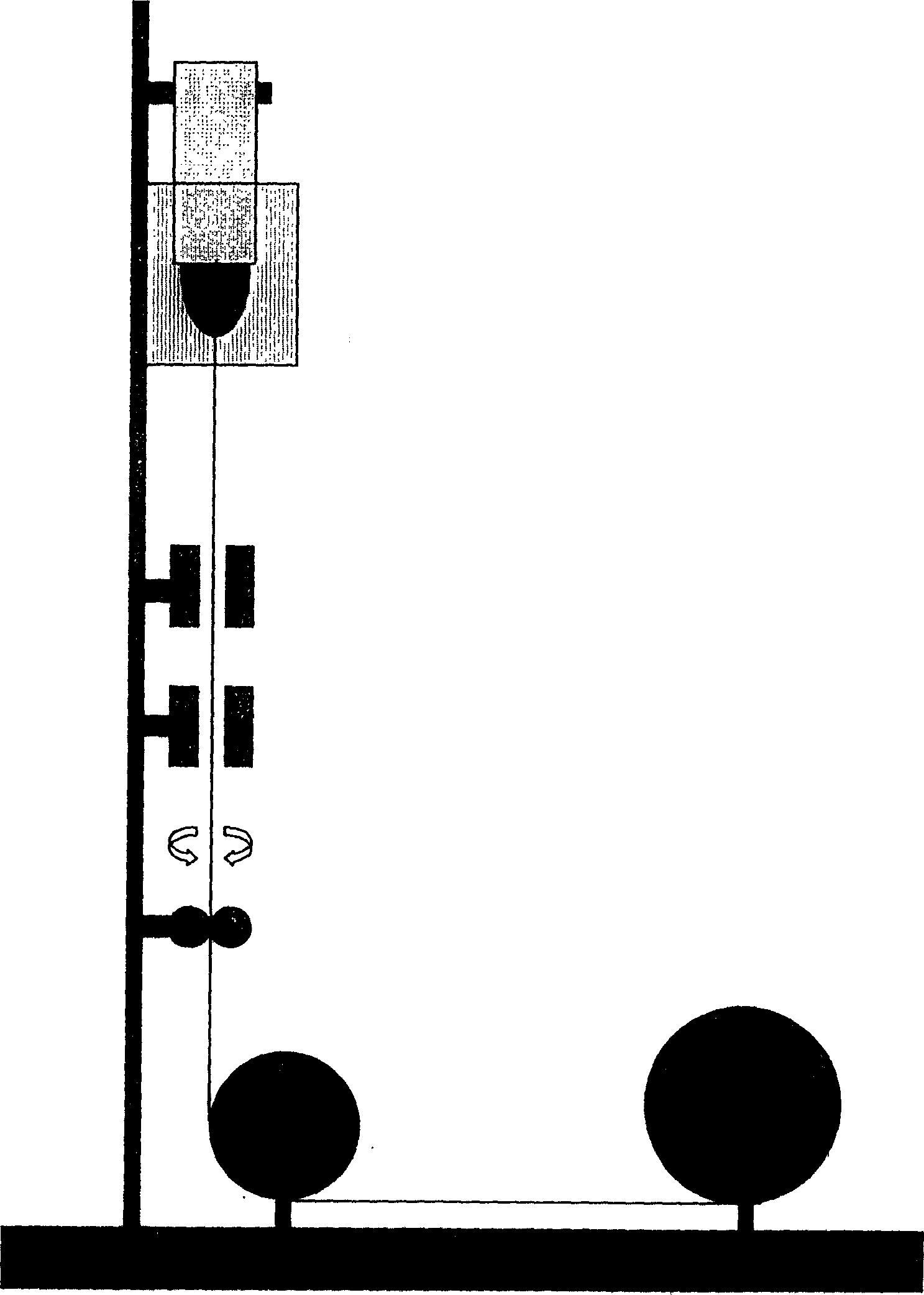
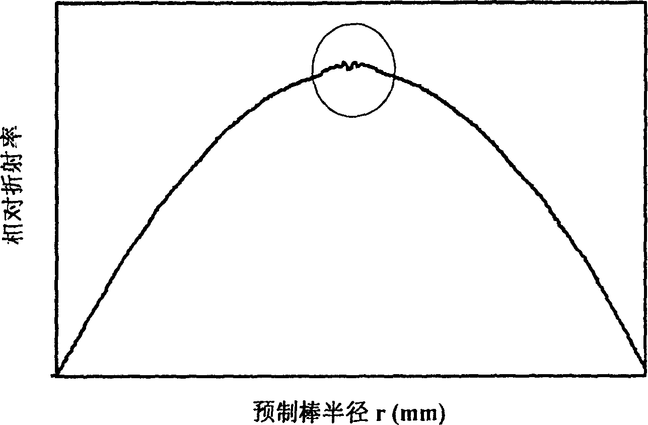
[0034] Such as figure 1 As shown, the multimode fiber 10 of the present invention includes a cladding 11 and a core 12. The diameters of the core and the cladding of the multimode fiber are 50 μm and 125 μm respectively, and its refractive index distribution is precisely optimized at a wavelength of 850 nm. The differential mode of the fiber The delay test curve is a continuous rising or falling curve, and its maximum change is less than 0.33ps / m, the full injection bandwidth is greater than 1500MHz·km at 850nm, greater than 600MHz·km at 1300nm, and the effective bandwidth is greater than 2000MHz·km and 1300nm respectively at 850nm and 1300nm 600MHz·km. The present invention adopts PCVD to deposit the cladding glass, and then deposits the core doped glass, the deposition rate is from 2.5g / min to 1.5g / min, the germanium vapor flow rate is from 3% to 60%, the number of depos...


PUM

PropertyMeasurementUnit
diameteraaaaaaaaaa
diameteraaaaaaaaaa

Abstract

The present invention relates to a multimode optical fiber and a manufacturing method thereof. The diameters of the core layer and the cladding layer of the multimode optical fiber are 50 μm and 125 μm respectively, and its refractive index distribution is precisely optimized at a wavelength of 850 nm. The differential mode delay test curve of the optical fiber is: A continuous rising or falling curve, and its maximum change is less than 0.22ps / m, the full injection bandwidth is greater than 1500MHz·km at 850nm, greater than 600MHz·km at 1300nm, and the effective bandwidth is greater than 2000MHz·km and 600MHz·km at 850nm and 1300nm respectively. In its manufacturing method, the deposition rate is from 2.5g / min to 1.5g / min, the flow rate of germanium vapor is from 3% to 60%, and the diameter of the shrinkage hole is controlled to be between 2 and 8mm in diameter during melting and shrinkage, and then the C 2 f 6 The corrosive gas corrodes the inner tube wall; the optical fiber is rubbed during the drawing process. The invention completely eliminates the center depression of the multi-mode optical fiber, reduces inter-mode delay, increases the bandwidth of the optical fiber, and can be used not only in high-speed network systems, but also in low-speed network systems.

Description

technical field [0001] The invention relates to an optical fiber and a manufacturing method thereof, in particular to a multimode optical fiber and a manufacturing method thereof. Background technique [0002] Multimode fiber is a data communication fiber used earlier in communication systems. Due to its large core diameter and numerical aperture, multiple stable conduction modes (usually more than a few hundred), large optical transmission energy and relatively loose technical requirements, multimode fiber has always been used in the field of optical communication. used. However, due to the existence of multiple transmission modes in the multimode fiber, the dispersion of the fiber is very large, which affects the application of the multimode fiber in high-speed networks. As we all know, the dispersion of optical fiber mainly includes material dispersion, waveguide dispersion and mode dispersion (also known as intermodal dispersion). For single-...

Claims


Application Information

Patent Timeline
Patent Type & Authority Patents(China)
IPC IPC(8): C03B37/018
Inventor 汪洪海汪松涂峰
Owner SICHUAN LEFEI OPTOELECTRONICS TECH CO LTD
Learn More