Complex twisting device for air-jet eddy-current spinning

A twister and vortex spinning technology, which is applied in the field of air-jet vortex spinning compound twisters, can solve the problems affecting the quality of yarn and finished fabric products, save the singeing process and waxing process, and improve wearing comfort , The effect of reducing production costs

Inactive Publication Date: 2005-05-04
DONGHUA UNIV
View PDF0 Cites 1 Cited by
  • Summary
  • Abstract
  • Description
  • Claims
  • Application Information

AI Technical Summary

Problems solved by technology

[0003] In order to overcome the above-mentioned shortcomings, the present invention provides a newly conceived air-jet vortex spinning compound twister, which is used to solve the problem of seriously affecting the production quality of yarn and finished fabrics due to the suction of some fibers from the exhaust port by the negative pressure eddy current field. question

Method used


Image

  • Complex twisting device for air-jet eddy-current spinning
  • Complex twisting device for air-jet eddy-current spinning
  • Complex twisting device for air-jet eddy-current spinning

Examples


Embodiment Construction

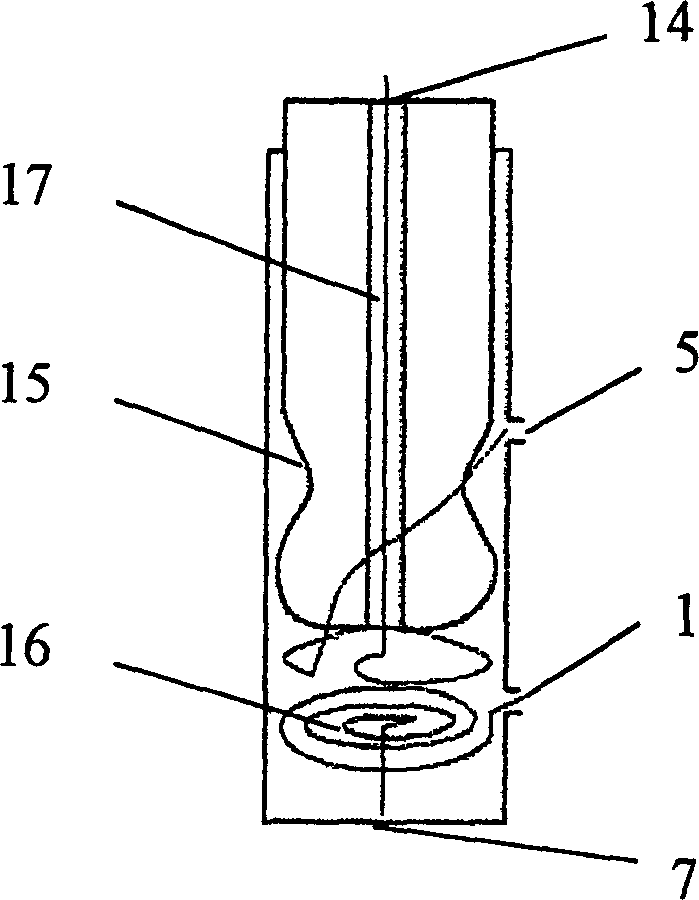
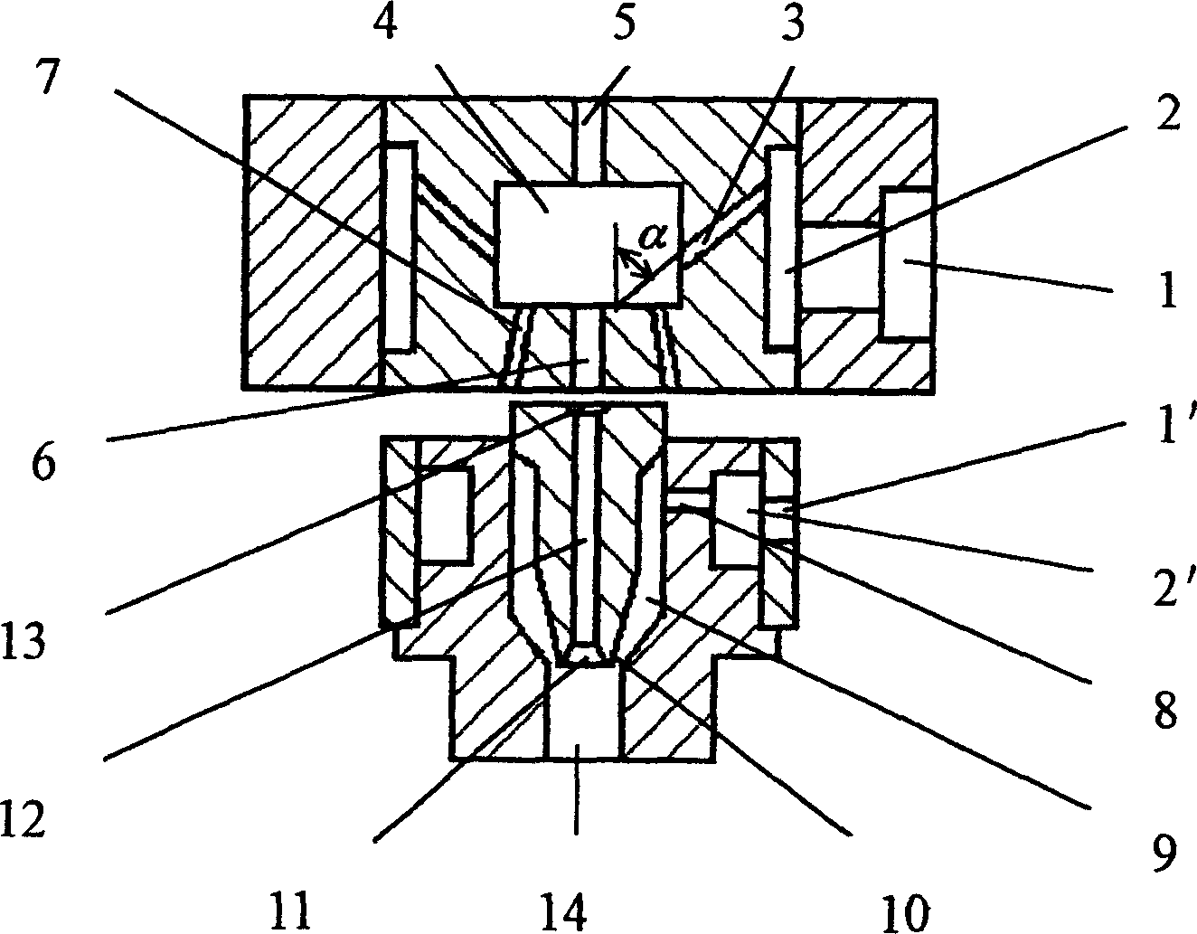
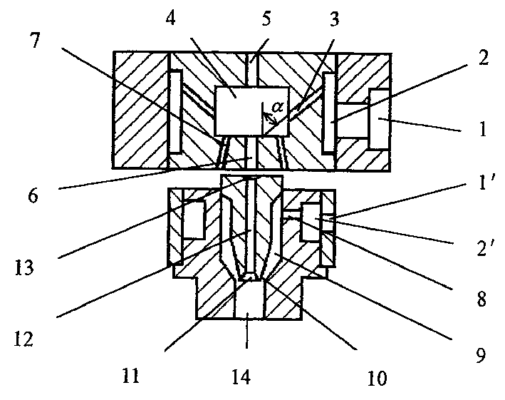
[0016] The present invention installs a newly conceived air-jet vortex spinning compound twister between the drafting area and the winding area of ​​the spinning machine. The air-jet vortex spinning compound twister is composed of an upper twister and a lower twister. It uses a positive pressure airflow to generate a vortex field and a pipe flow. The fibers enter the vortex field through the conveying pipe, and the fiber strands rotate with the high-speed rotating airflow. While the fiber strands are rotating at high speed, the pipe flow protects and guides the twisting fiber strands to leave the eddy current field quickly, during which the fiber strands complete the twisting and produce twisted yarn at high speed. Such as figure 2 As shown, the upper twister generates a positive pressure vortex field through the positive pressure airflow generated by the compressor, and the negative pressure in the center of the vortex field sucks the fiber flow and drives the fiber strands ...


PUM

PropertyMeasurementUnit
diameteraaaaaaaaaa
diameteraaaaaaaaaa
diameteraaaaaaaaaa

Abstract

The invention belongs to the textile field and provides an air-jet vortex spinning compound twister for twisting fiber strands by using an air-jet vortex. The compound twister is composed of an upper twister and a lower twister. It uses positive pressure airflow to generate vortex field and pipe flow, and the fiber enters the vortex field through the conveying pipe. The fiber strands rotate with the high-speed rotating air flow. While the fiber strands are rotating at high speed, the pipeline flow protects and guides the fiber strands being twisted to leave the eddy current field quickly. During this process, the fiber strands are twisted and produced at high speed. There are twisted yarns. By adopting the invention, high-quality yarn can be produced at low cost and high speed.

Description

Technical field: [0001] The invention belongs to the textile field, and relates to an air-jet vortex spinning compound twister. Background technique: [0002] The existing vortex spinning is a negative pressure air twisting spinning technology, such as figure 1 As shown, it draws air through the exhaust port 7, the air flow enters from the air inlet 1, and the air flow entering the vortex tube 15 forms a negative pressure vortex 16, and the negative pressure vortex field sucks the fiber from the fiber inlet 5, and the rotating vortex The input fiber is twisted by the field, and the twisted yarn is output from the upper end from the yarn drawing tube 17 through the yarn outlet 14 . Since this kind of fiber is sucked by the negative pressure eddy current field, some fibers will be sucked away from the exhaust port 7 by the air flow during the processing, which seriously affects the uneven thickness of the yarn and the production rate of the product, and also affects the quali...

Claims


Application Information

Patent Timeline
Patent Type & Authority Patents(China)
IPC IPC(8): D01H1/14D01H4/02D01H4/08D01H7/00D01H7/86
Inventor 程隆棣祝章琛于修业劳继红江慧薛文良
Owner DONGHUA UNIV
Why Eureka
Try Eureka