
Concentric Wheel Piston assembly

A technology of concentric wheels and assemblies, applied in belts/chains/gears, machines/engines, mechanical equipment, etc., can solve problems such as waste of materials, large space, limited ratio difference range, etc., and achieve the effect of wide adaptability

Inactive Publication Date: 2005-05-18
马兴宝
View PDF1 Cites 0 Cited by
  • Summary
  • Abstract
  • Description
  • Claims
  • Application Information

AI Technical Summary

Problems solved by technology

[0003] In the piston pumps and power machines made of the traditional transmission mechanism of the connecting rod crankshaft, due to the inherent shortcomings of the connecting rod crankshaft itself, there are many problems in the piston located on the small end of the connecting rod, for example, Because of the side pressure component N of the connecting rod crankshaft, it will cause the wear of a specific part between the cylinder plugs to intensify, causing harmful deformation of the cylinder walls on both sides in the direction of the N component force, and then gradually forming leakage. As a result, the effective sealing effect cannot be sustained and constant, which will affect the working conditions and efficiency, and even cause serious problems such as cylinder seizure and cylinder destruction
As another example, due to the asymmetry and unbalanced operation of the connecting rod crank mechanism, it is necessary to add a balance weight and a flywheel mechanism to improve the movement of the piston, but this is only an improvement and cannot completely solve the problem
For another example, because the piston located on the small end of the connecting rod always turns back in a straight line according to the inherent trajectory of its particle motion, and the existence of the radial component force R, the piston not only has an insurmountable dead point effect and more Inertia loss, and when the piston and the connecting rod reciprocate, the impact vibration caused by the joint is also relatively large, and there is also an obvious swing phenomenon
In addition, because the length of the connecting rod and the radius of the crank are operated together, and the space required for one round of reciprocating operation is large, it not only increases the volume and weight of the casing, but also limits the range of the ratio difference between the piston bore and the piston stroke ( See Table 1), which wastes materials and is not conducive to expanding the bore to increase the working volume

Method used


Image

  • Concentric Wheel Piston assembly
  • Concentric Wheel Piston assembly
  • Concentric Wheel Piston assembly

Examples


Embodiment Construction

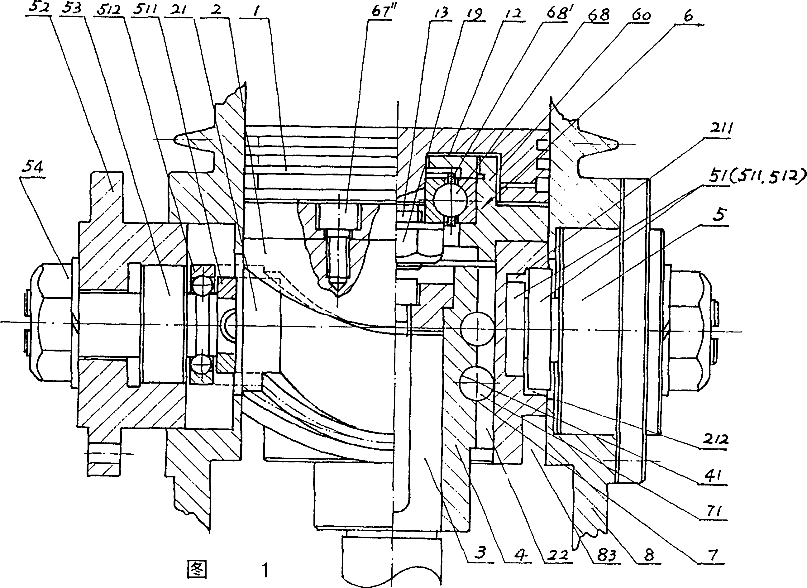
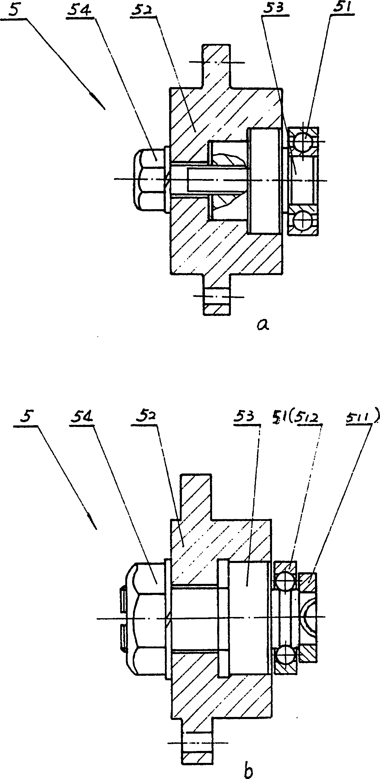
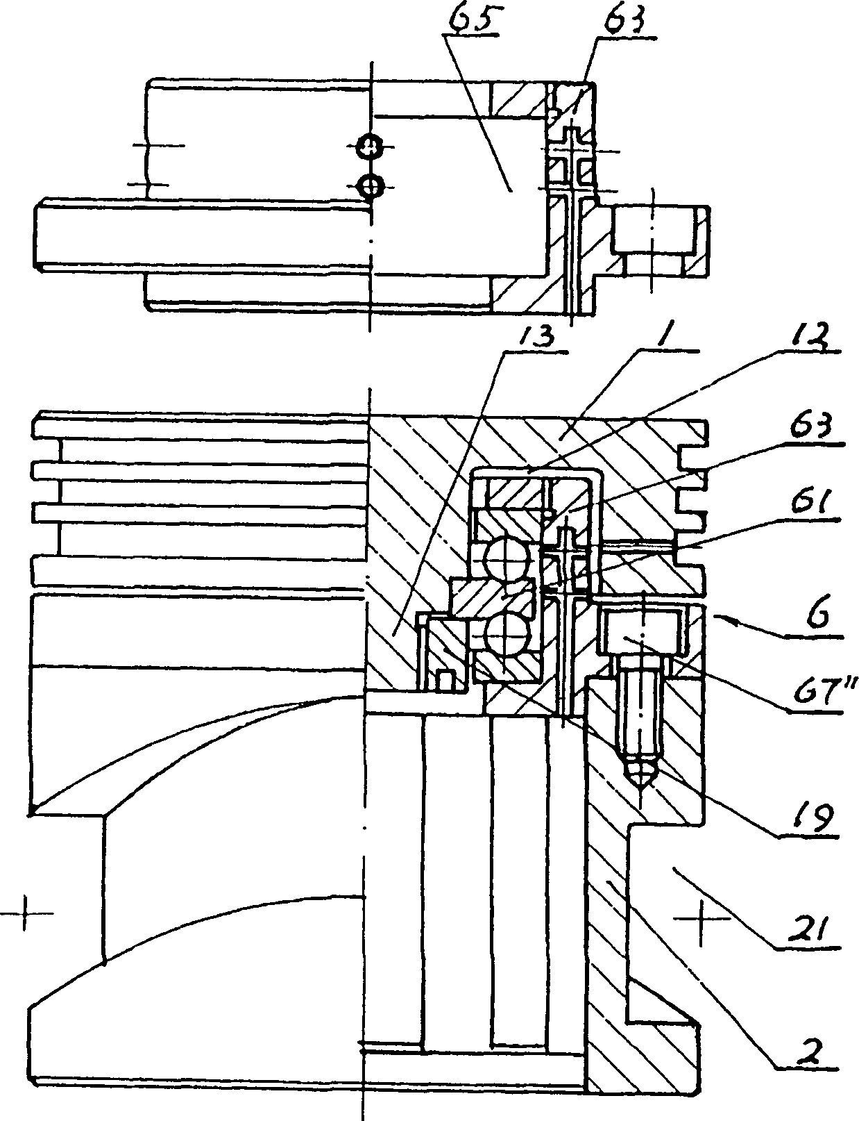
[0043] As shown in Figure 1, the concentric wheel piston assembly of the present invention comprises piston head 1, concentric wheel 2, straight shaft 3, the straight shaft wheel 4 that is detachably fixed on straight shaft 3, its bead head 51 and concentric wheel 2 The sinusoidal ball 5 engaging the peripheral chordal groove 21 , the connecting means 6 connecting the piston head 1 to the concentric wheel 2 , the movement pair 7 between the concentric wheel 2 and the straight axis wheel 4 and the housing 8 . The concentric wheel-piston assembly of the present invention also involves a sealing structure and a lubricating oil passage structure, but the content in this aspect is not within the protection scope of the present invention, so these content will not be described again.

[0044] In order to facilitate the understanding of the present invention, the positional relationship among the various parts of the concentric wheel-piston assembly of the present invention and the ov...


PUM


Abstract

This is the continuation of the invention patent No. ZL85106590, which was originally named "concentric wheel". The purpose is still to replace the connecting rod crank. Parts and components make the schematic diagram evolve into a concrete sample diagram. Bearing-type circular grooves and balls pass through the connecting frame, and the piston rod connects the piston head and the concentric wheel in various ways to form a variety of concentric wheel-piston assemblies as the name of the invention; bimodal sine groove and sine ball Overlapping chordal grooves and tower sine balls are formed respectively; while ball spline-like straight grooves and beads form straight-axis wheels. The present invention inherits obvious advantages such as symmetry, compactness, high efficiency and cylindrical cylinder that concentric wheel has, and does not have the fatal flaw of connecting rod crankshaft type piston mechanism at all. At the same time, it also solves the phenomenon that the sinusoidal ball itself changes direction frequently in the rotation of the single groove structure, so that the transmission performance is further optimized.

Description

(1) Technical field [0001] The invention relates to a piston head, in particular to a concentric wheel-piston assembly combined with a concentric wheel. [0002] The present invention is the continuation of the invention patent of No. ZL85106590, named concentric wheel. (2) Background technology [0003] In the piston pumps and power machines made of the traditional transmission mechanism of the connecting rod crankshaft, due to the inherent shortcomings of the connecting rod crankshaft itself, there are many problems in the piston located on the small end of the connecting rod, for example, Because of the side pressure component N of the connecting rod crankshaft, it will cause the wear of a specific part between the cylinder plugs to intensify, causing harmful deformation of the cylinder walls on both sides in the direction of the N component force, and then gradually forming leakage. As a result, the effective sealing effect cannot be sustained and constant, and as a res...

Claims


Application Information

Patent Timeline
Patent Type & Authority Patents(China)
IPC IPC(8): F02B75/32F16H21/16
Inventor 马兴宝
Owner 马兴宝
Learn More