Adjusting device and method for flash memory array after erasion

A flash memory array and adjustment device technology, applied in information storage, static memory, read-only memory, etc., can solve problems affecting the reliability of storage unit A, abnormal critical voltage offset, etc.

Inactive Publication Date: 2005-11-02
MACRONIX INT CO LTD
View PDF0 Cites 1 Cited by
  • Summary
  • Abstract
  • Description
  • Claims
  • Application Information

AI Technical Summary

Problems solved by technology

As shown in the figure, memory cell A is at 10 3 Seconds later, there will be an abnormal threshold voltage shift, which is because the residual electrons in memory cell A have not been completely removed, which will affect the reliability of memory cell A

Method used


Image

  • Adjusting device and method for flash memory array after erasion
  • Adjusting device and method for flash memory array after erasion
  • Adjusting device and method for flash memory array after erasion

Examples


Embodiment Construction

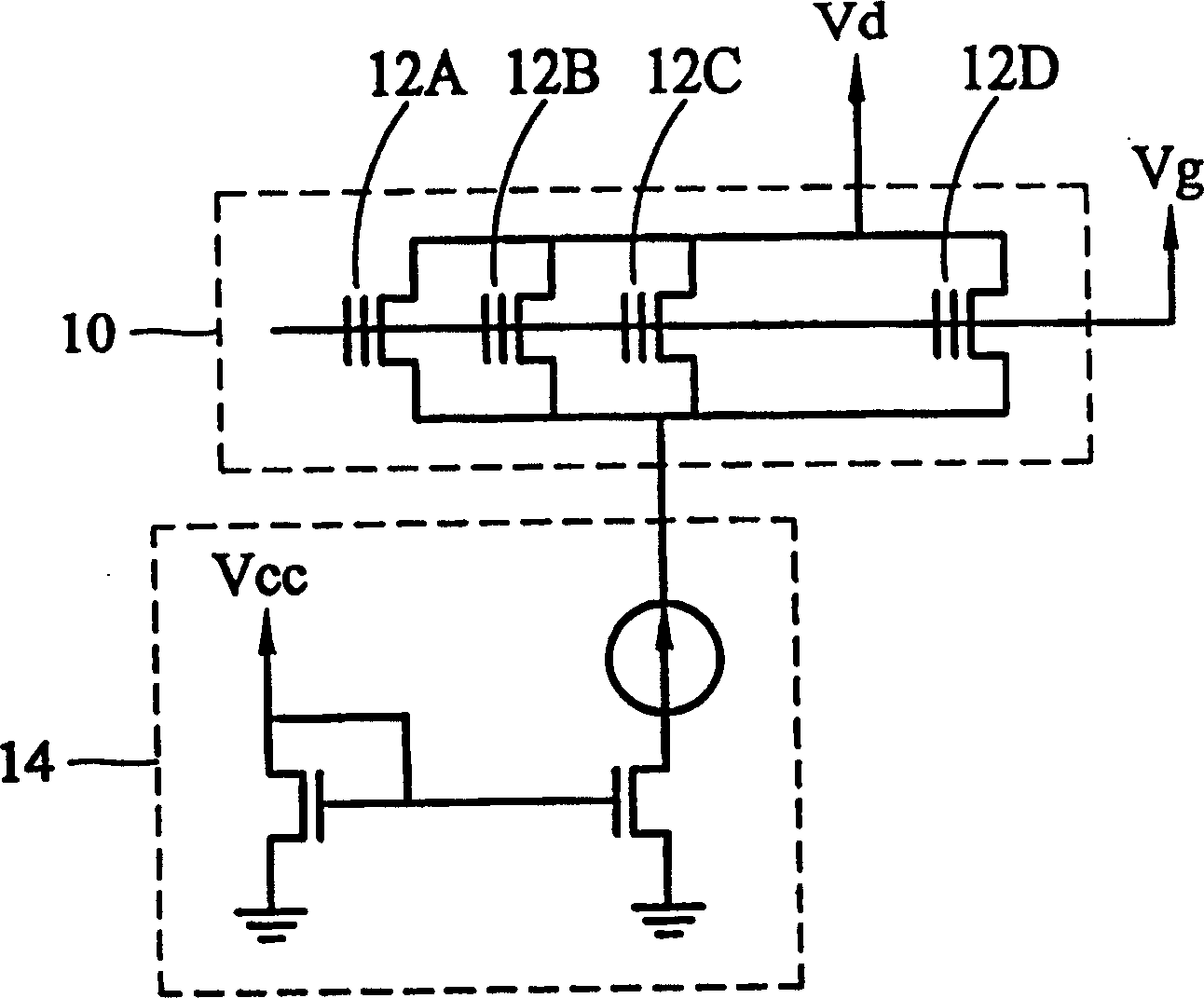
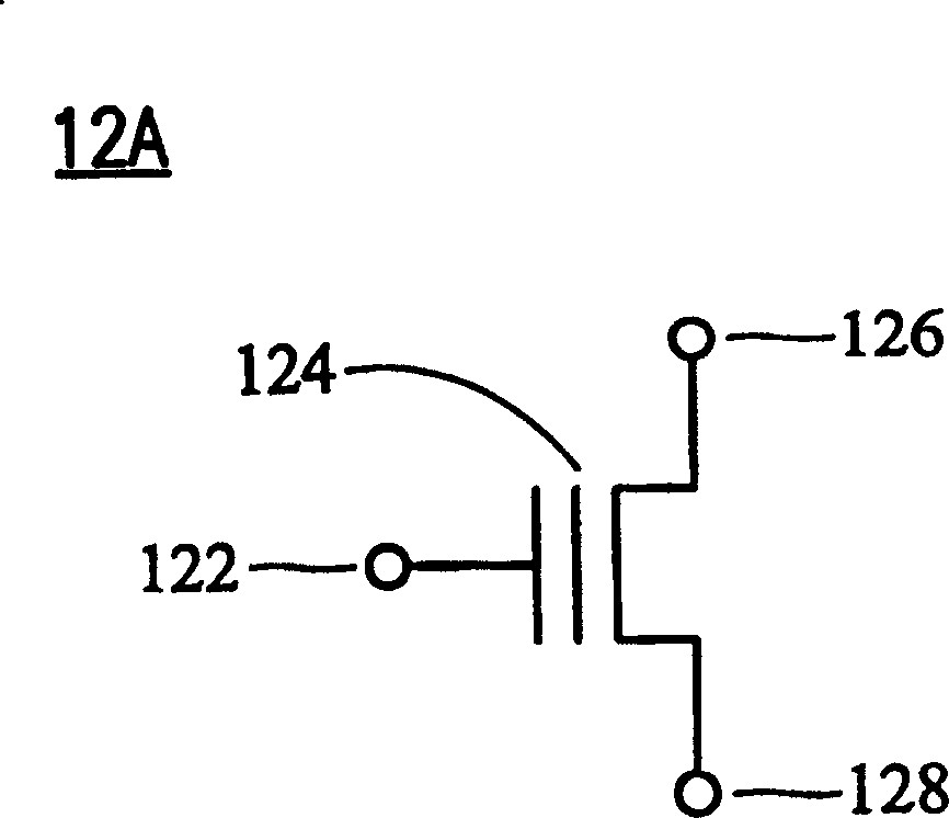
[0022] Figure 5 It is a schematic circuit diagram of post-erasing processing of a flash memory array according to an embodiment of the present invention. Wherein, the storage array 20 has a plurality of storage units 22A, 22B, 22C, and 22D, where a flash memory unit is taken as an example. The structure and structure represented by each part of the flash memory unit 22A, 22B, 22C, 22D in the circuit symbol figure 2 are the same and will not be repeated here. The flash memory cell 22A has a control gate 122 , a floating gate 124 , a drain 126 and a source 128 .

[0023] The drain voltage supplied by the drain power supply device 24 to the flash memory units 22A, 22B, 22C, and 22D ranges from 2.5V to 5V, and the source is coupled to a constant current supplier 26 for receiving a current of about 100uA to 2mA. , the current intensity depends on different post-erase processing requirements. In addition, the control gate of the flash memory unit according to the embodiment of...


PUM


Abstract

The regulator suitable for memory array with several flash memory units, each of which includes one control grid, one floating grid, one source and one drain. The regulator includes one drain power source, constant current source and control grid source. The drain power source provides one positive voltage to the drain of the flash memory unit, the constant current source provides a source current to the source of the flash memory unit, and the control grid source provides a gradually raised grid voltage to the control grid of the flash memory unit to control the source current to the flash memory unit and gradually change the critical voltage value of the flash memory unit.

Description

technical field [0001] The invention relates to a flash memory array post-erasing adjustment device and method, in particular to a flash memory array post-erasing adjustment device and method for gradually increasing the voltage of the control grid for post-erasing processing. Background technique [0002] The programming and erasing processing methods of traditional flash memory cells are mainly realized by using the channel hot electron effect (channel hot electron effect) in programming, that is, using the positive voltage coupled to the floating gate and the current between the channel below it. The voltage difference creates an electric field of sufficient strength, allowing electrons to obtain sufficient kinetic energy (ie, hot electrons) to penetrate the oxide layer and to be trapped in the floating gate. Specifically, since the existence of electrons in the floating gate can affect the conduction of the channel below it, so by injecting electrons into the floating ga...

Claims


Application Information

Patent Timeline
Patent Type & Authority Patents(China)
IPC IPC(8): G11C16/10G11C16/14
Inventor 范左鸿叶致锴卢道政
Owner MACRONIX INT CO LTD
Why Eureka
Try Eureka