Elastic surface wave filter, wave divider and communication machine

A surface acoustic wave and filter technology, applied in instruments, impedance networks, electrical components, etc., can solve problems such as reflection characteristics, attenuation characteristics difficulties, etc.

Inactive Publication Date: 2006-04-19
MURATA MFG CO LTD
View PDF3 Cites 4 Cited by
  • Summary
  • Abstract
  • Description
  • Claims
  • Application Information

AI Technical Summary

Problems solved by technology

Therefore, in the current structure, it is difficult to optimize both the reflection characteristics and the attenuation characteristics.

Method used


Image

  • Elastic surface wave filter, wave divider and communication machine
  • Elastic surface wave filter, wave divider and communication machine
  • Elastic surface wave filter, wave divider and communication machine

Examples


Embodiment 1

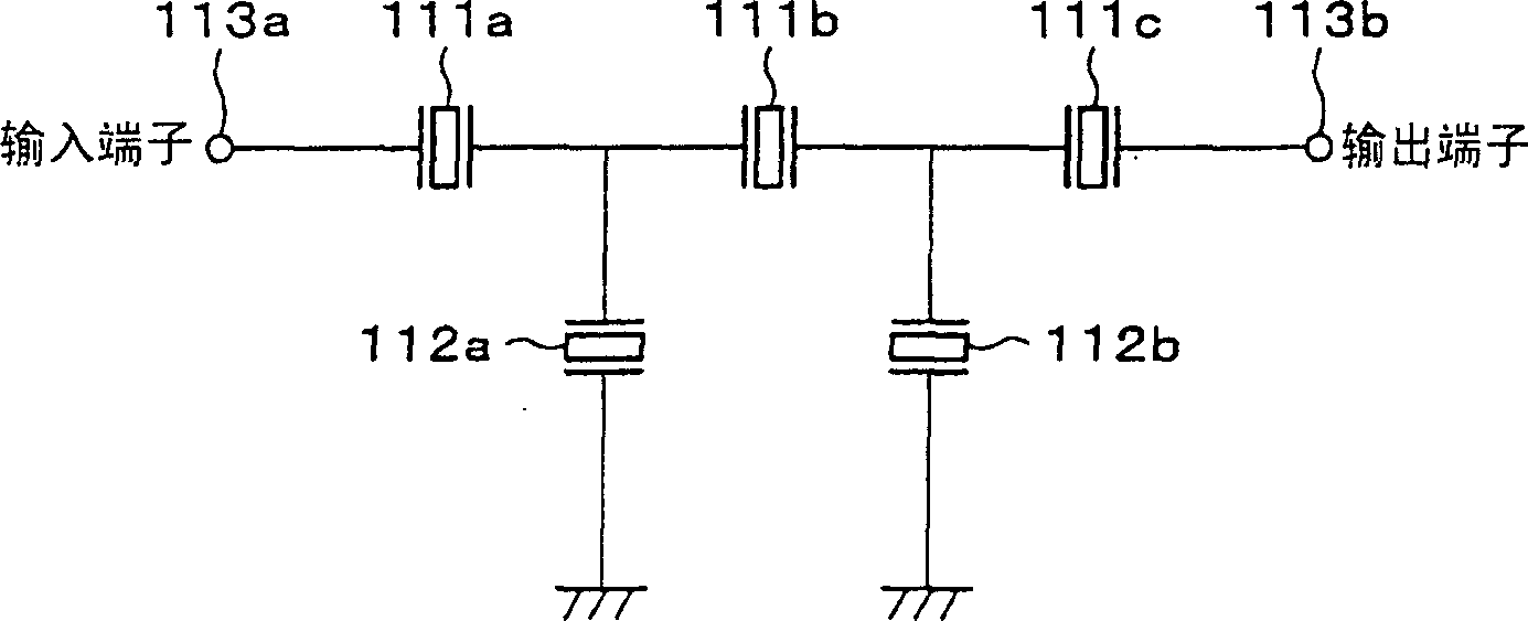
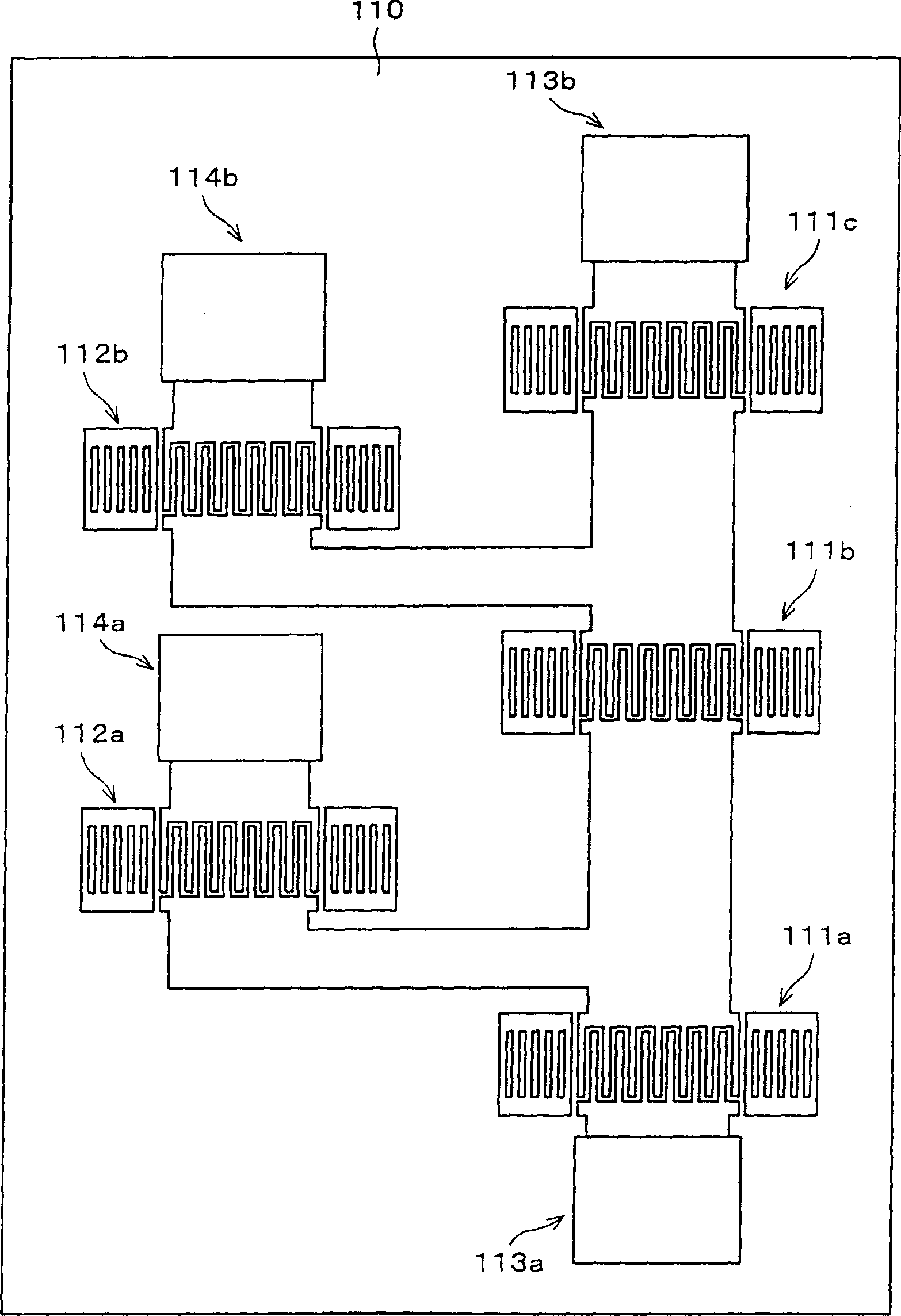
[0066] As the surface acoustic wave filter of the first embodiment, a ladder-type filter is applied, and the center frequency of the transmission band is 1441 MHz Tx filter. The above SAW filter, such as figure 1 the wiring diagram of the figure 2 As shown in the schematic configuration diagram of , on the piezoelectric substrate 110 , the series resonators 111 a to 111 c and the parallel resonators 112 a and 112 b are arranged in a ladder shape.

[0067] The series resonators 111a to 111c and the parallel resonators 112a and 112b are arranged such that the propagation directions of the surface acoustic waves thereof are substantially parallel to each other, but it is desirable to achieve miniaturization.

[0068] In addition, the series resonators 111a to 111c are connected in series between the input terminal 113a and the output terminal 113b, and are arranged side by side in a direction substantially perpendicular to the propagation direction of the surface acoustic wave...

Embodiment 2

[0099] Embodiment 2 of the surface acoustic wave filter of the present invention is a filter for Rx in a frequency band with a center frequency of 1489 MHz using a ladder filter. Figure 12 Represent the circuit diagram of embodiment 2, Figure 13 A schematic configuration diagram showing the IDT electrodes on the piezoelectric substrate 110 . In the surface acoustic wave filter, the parallel resonators 212a, 212b, and 212c and the series resonators 211a and 211b are disposed on the piezoelectric substrate 110 referring to the first embodiment described above.

[0100] In the surface acoustic wave filter described above, the input side starts with the parallel resonator 212a, and the output side ends with the parallel resonator 212c, thereby forming a π-shaped structure. Here, as long as the parallel resonators 212a and 212b are connected to the input and output terminals 213b and 213a, it is called a π-shaped structure regardless of the combination of series and parallel res...


PUM


Abstract

A surface acoustic wave filter includes a piezoelectric substrate (110) and a plurality of one-terminal-pair surface acoustic wave resonators (111,112), which are disposed on the piezoelectric substrate in a ladder pattern and each of which includes an IDT electrode having a pair of comb electrodes. The one-terminal-pair surface acoustic wave resonators disposed in a ladder pattern include series resonators (111a-c), all of which are thinned-out. The electrode pitch of the IDT electrode of at least one (111b) of the series resonators is different from that of the IDT electrodes of the other series resonators (111a,c).

Description

technical field [0001] The present invention relates to a surface acoustic wave filter used as a bandpass filter, and more specifically, to a ladder-shaped surface acoustic wave filter in which one terminal pair of surface acoustic wave resonators is arranged into multiple, Splitter and communication machine. Background technique [0002] Conventionally, a surface acoustic wave filter using a one-terminal-pair surface acoustic wave resonator has been developed as a filter used in a high-frequency (RF, especially GHz band or higher) band of a communication device such as a mobile phone. The above-mentioned surface acoustic wave filter has many superior characteristics, such as: small and light, excellent shock resistance and impact resistance, small product error and high reliability, and can realize assembly automation due to the realization of no adjustment of the circuit, Simplification, and even if high frequency is achieved, manufacturing is easy. [0003] In addition,...

Claims


Application Information

Patent Timeline
Patent Type & Authority Patents(China)
IPC IPC(8): H04Q7/32H03H9/25H03H7/46H03H9/10H03H9/145H03H9/64H03H9/72
CPCH03H9/14517H03H9/1071H03H9/6483G09B23/188
Inventor 高田俊明
Owner MURATA MFG CO LTD
Why Eureka
Try Eureka