Optical transmitter and optical transmission system

An optical transmitter and light source technology, applied in transmission systems, electromagnetic wave transmission systems, optical multiplexing systems, etc., can solve problems such as difficulty in waveform compensation, changes in design and manufacturing, and voltage drop in electronic devices, and achieve reflection characteristics. Improvement, realization of high-speed, easy-to-speed effect

Inactive Publication Date: 2007-10-31
NIPPON TELEGRAPH & TELEPHONE CORP
View PDF1 Cites 11 Cited by
  • Summary
  • Abstract
  • Description
  • Claims
  • Application Information

AI Technical Summary

Problems solved by technology

In this regard, it becomes difficult to implement an ideal electrical installation in the high frequency band, especially it is difficult to terminate the reflected wave in the blocking region of the filter.
In addition, when the ideal roll-off characteristics of the electric filter are realized, as the transmission speed increases, the frequency-dependent loss and dispersion of the transmission line and the filter will occur, resulting in waveform distortion.
Therefore, there is a problem that compensation of the waveform becomes difficult.
[0022] In addition, when considering the situation of the wavelength multiplexing system of the existing RZ-based PSK signal, in order to realize the suppression of mutual phase modulation, the optical modulation frequency band is extended to about 4 times of the transmission speed, considering the 0.4bit / s / When the density is higher than Hz, there will be a problem that the transmission quality will deteriorate due to crosstalk
In addition, when considering high speed in the prior art, the baseband signal input to the modulator must be processed for high speed.
[0023] However, with the increase in transmission speed, the withstand voltage of electronic devices generally tends to decrease, and there is a disadvantage that it is difficult to realize large-amplitude operations such as modulator drive.
Moreover, it becomes difficult for the precoding circuit to realize its high-speed operation, and it is necessary to change the design and manufacture every time the transmission speed increases.

Method used


Image

  • Optical transmitter and optical transmission system
  • Optical transmitter and optical transmission system
  • Optical transmitter and optical transmission system

Examples


Embodiment Construction

[0088] The following embodiments do not limit the inventions related to the claims, and combinations of features described in the embodiments are not limited to those necessary for all the means to solve the invention.

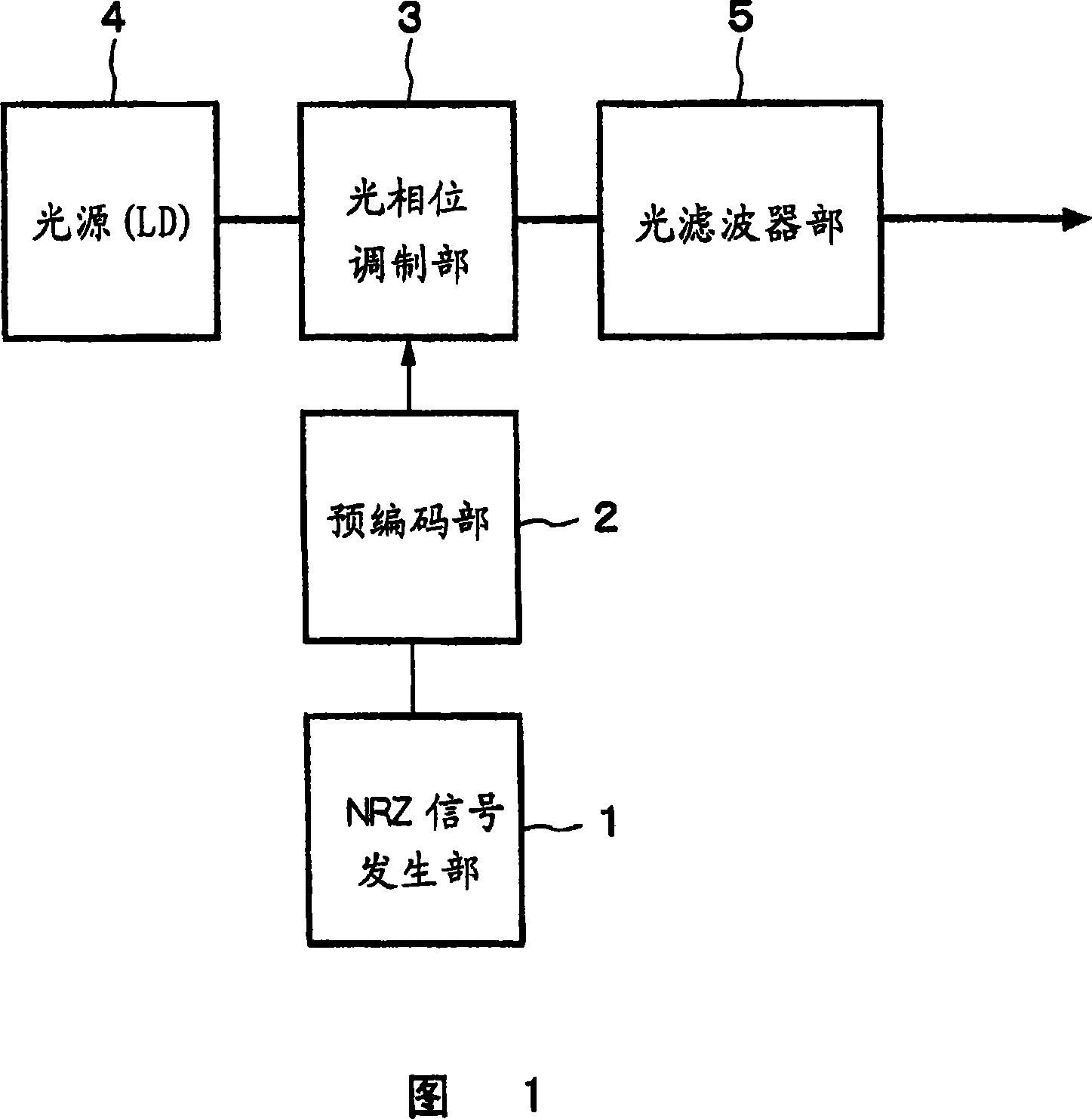
[0089] FIG. 1 is a block diagram of an embodiment of an optical transmitter in the present invention. In FIG. 1 , a binary NRZ electrical signal output from an NRZ signal generation unit 1 is input to a precoding unit 2 . Signal processing is performed in the precoding unit 2 so that the output of the optical transmitter matches the input NRZ signal. The differential precoded NRZ signal generated in the precoding unit 2 is amplified as necessary and input to the optical phase modulation unit 3 .

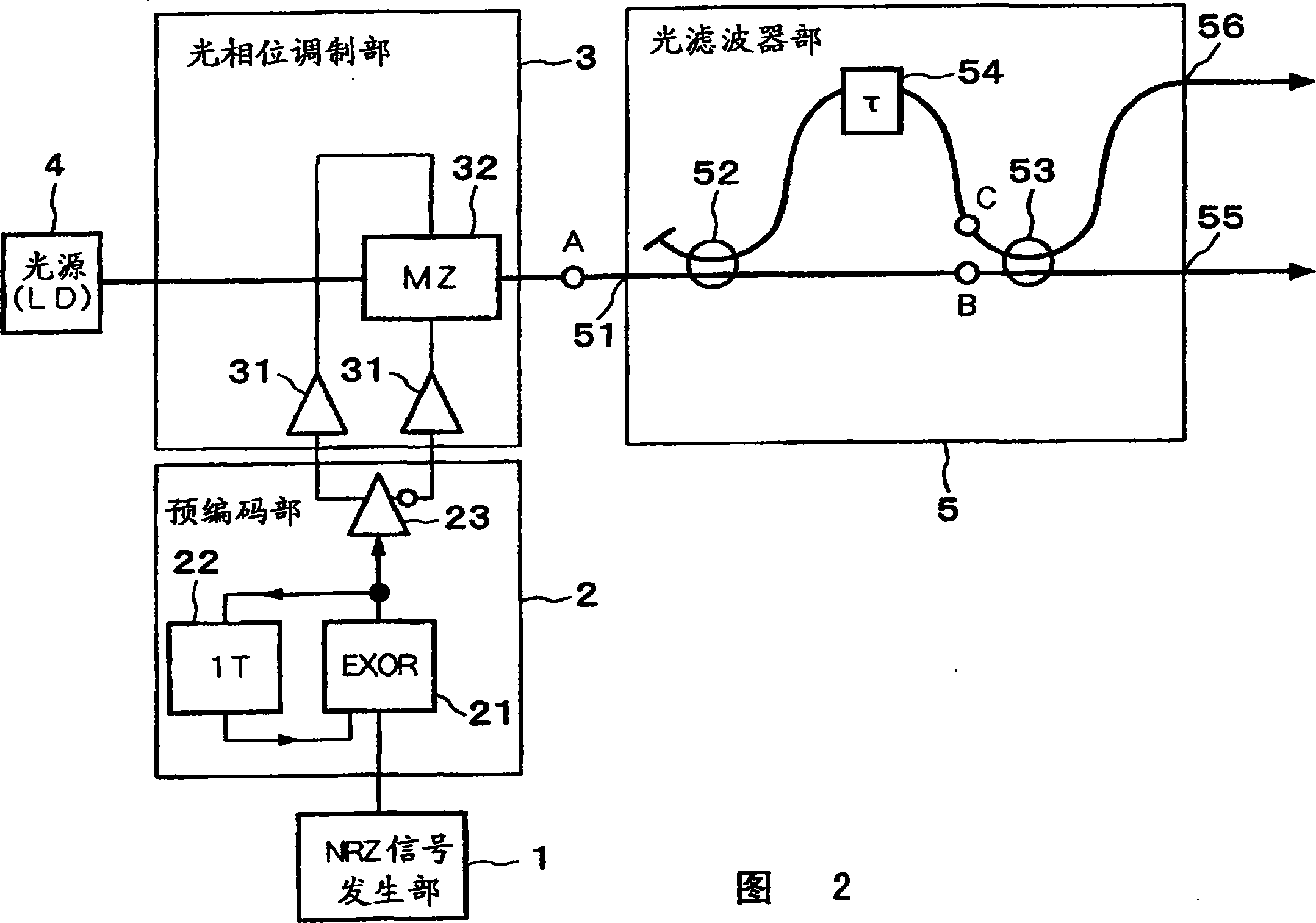
[0090] The single longitudinal mode CW optical signal emitted from the light source 4 (LD; Laser Diode) is input to an optical filter that converts the optical phase modulation signal into an RZ intensity modulation signal after performing appropriate phase modulati...


PUM


Abstract

The present invention suppresses to a minimum the degradation of the transmission quality caused by chromatic dispersion characteristic of an optical transmission medium, and the interplay between the chromatic dispersion and non-linear optical effects in dense WDM transport systems. A baseband input data signal is pre-coded in advance by a pre-coding unit, phase modulation is carried out using a pre-coded signal by the optical phase modulating unit, and the phase modulated optical signal is converted to an RZ intensity modulated signal by the optical filter unit that performs phase-shift-keying to amplitude-shift-keying conversion. For example, an optical phase modulating unit generates an encoded DPSK phase modulated signal using a differential phase shirt keying (DPSK) format, and a phase modulated signal is converted to an RZ intensity modulated signal by the optical filter unit disposed downstream of the optical phase modulating unit.

Description

technical field [0001] The present invention relates to an optical transmitter and an optical transmission system capable of minimizing the wavelength dispersion existing in an optical transmission medium such as an optical fiber, or the degradation of transmission quality caused by the interaction between the wavelength dispersion and nonlinear optical effects . [0002] This application is based on Japanese Patent Application No. 2001-199467, and the related content can be referred to here. Background technique [0003] In order to minimize the wavelength dispersion existing in optical fiber and other transmission media, or the degradation of transmission quality caused by the interaction of wavelength dispersion and nonlinear optical effects, and use the RZ (Return-to -Zero) light intensity modulation code is proposed. [0004] For example, document 1 (Y.Miyamoto et.al. "Duobinary carrier-suppressed return-to-zero format and its application to100GHz-spaced 8×43-Gbit / s D...

Claims


Application Information

Patent Timeline
Patent Type & Authority Applications(China)
IPC IPC(8): H04B10/155H04B10/18G02F1/01H04B10/2507H04B10/2513H04B10/516H04B10/548H04B10/556H04B10/588H04B10/61
CPCH04B10/677H04J14/0227H04B10/5561H04J14/0279H04B10/5051H04J14/0246H04B2210/517H04B10/516H04B10/5162H04B10/5055
Inventor 宫本裕平野章桑原昭一郎富泽将人
Owner NIPPON TELEGRAPH & TELEPHONE CORP
Why Eureka
Try Eureka