Baking method for ceramic plate and producing method
A technology of ceramic plates and ceramics, which is applied in the firing field of piezoelectric ceramic plates, which can solve problems such as damage, sticking to the mounting positioner, and poor shape, and achieve the effect of preventing warping or bending
- Summary
- Abstract
- Description
- Claims
- Application Information
AI Technical Summary
Problems solved by technology
Method used
Image
Examples
Embodiment approach 1
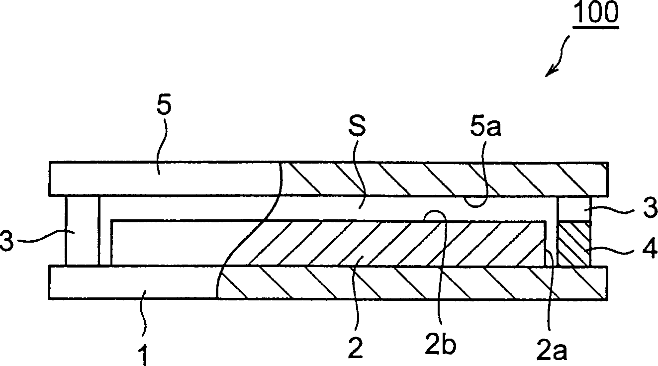
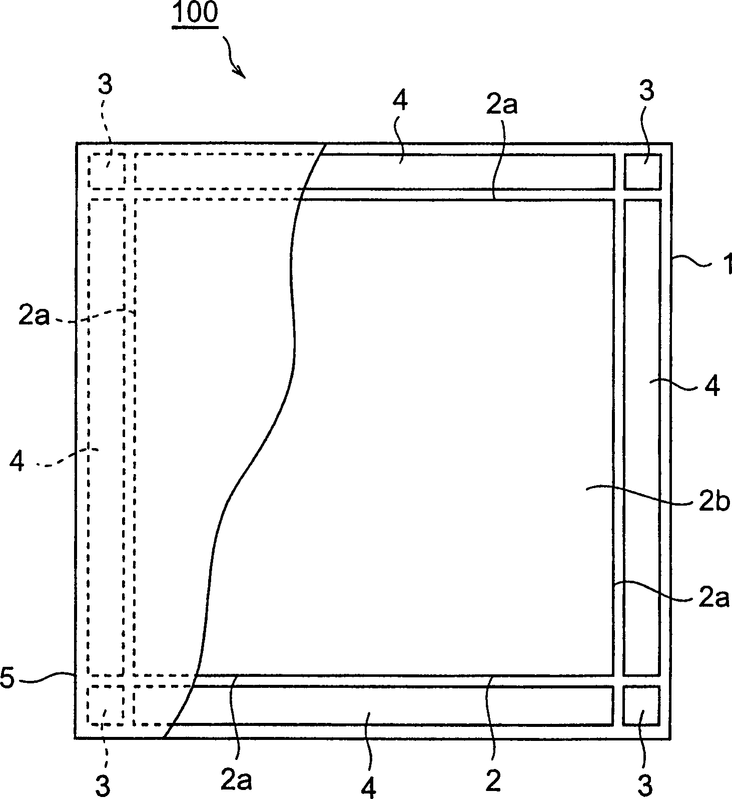
[0070] First, refer to Figure 1-Figure 3 Embodiment 1 of the present invention will be described.
[0071] Such as figure 1 with figure 2 As shown, a ceramic plate 2 is mounted on a dense (porosity of 3% or less, more preferably a porosity of 1% or less) zirconia mounting positioner (first holding member) 1 formed in a square shape of 100 mm×100 mm. . Since the zirconia mounting positioner 1 has low reactivity with the ceramic plate 2 during firing and has good durability, it is preferably completely stabilized with 8 mol% to 12 mol% of yttrium oxide (Y2O3). In addition, the ceramic plate 2 is made of piezoelectric ceramics containing lead zirconate titanate (specifically, PbTiO 3 -PbZrO 3 -Pb(Mg1 / 3Nb2 / 3)O 3 -Pb(Zn1 / 3Nb2 / 3)O 3 A single plate made of 4 components such as piezoelectric ceramics) was produced as follows.
[0072] That is, materials in the form of oxides or carbonates are wet-mixed by a ball mill, and intermediate firing is carried out at 950 degrees aft...
Embodiment approach 2
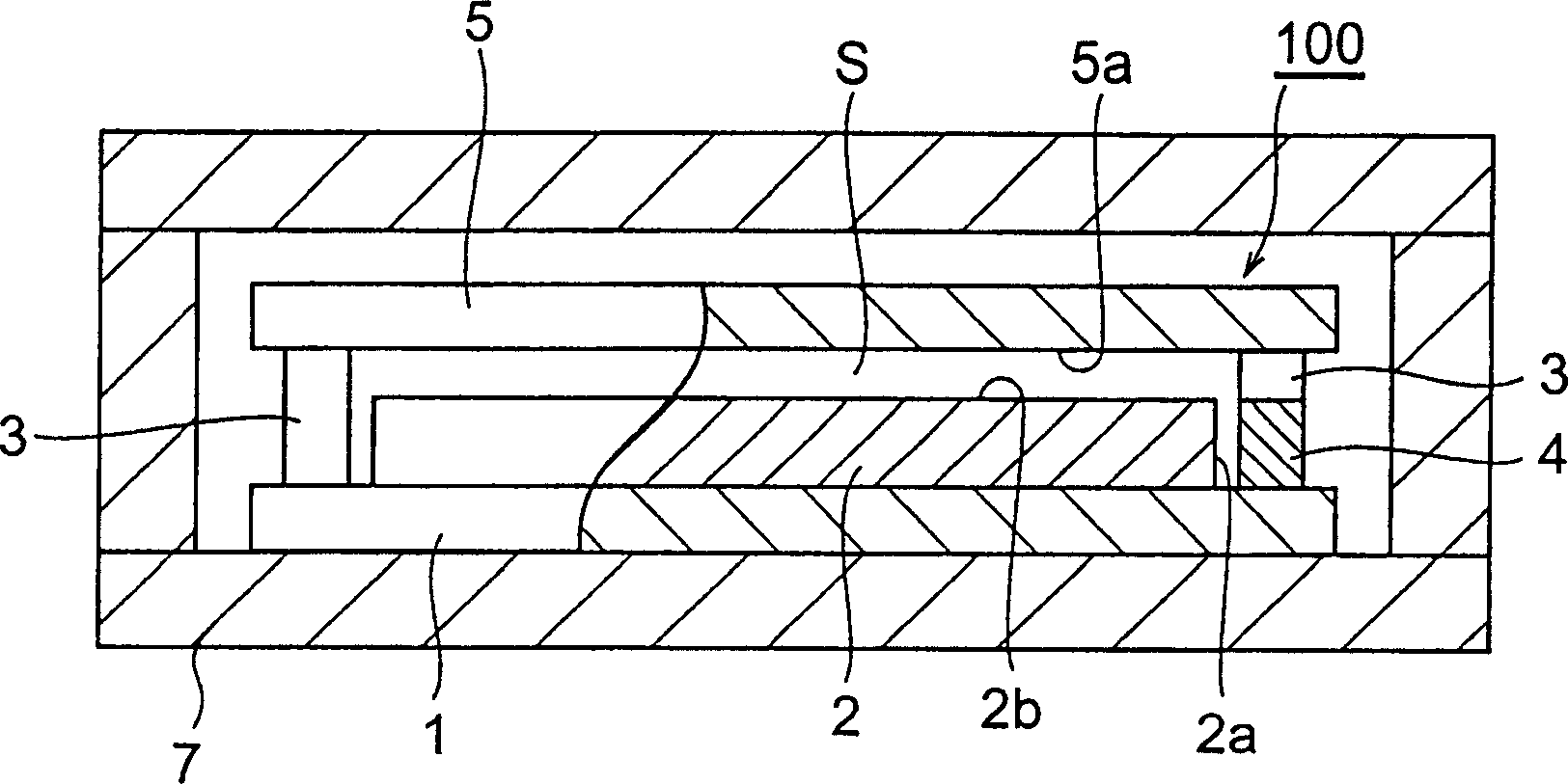
[0084] Refer below Figure 2-Figure 5 Embodiment 2 of the present invention will be described.
[0085] In the method of firing a ceramic plate according to Embodiment 2, a laminate of ceramic sheets in which electrodes are patterned is used as the ceramic plate 2 . Ten ceramic plates 2 were taken out by press-cutting from the press-treated green sheet laminate (ceramic raw material), and formed into a rectangular thin plate shape [33 mm×12 mm, thickness 0.375 mm]. In addition, the ceramic plate 2 is subjected to polarization treatment or the like after firing as described below, and becomes a multilayer piezoelectric element.
[0086] Such as Figure 4 with Figure 5 As shown, ten ceramic plates 2 cut out from the laminated body of green sheets were loaded on a zirconia mounting setter 1 and arranged in a matrix of 2 rows and 5 columns at the center of the zirconia mounting setter 1 . In addition, four rod-shaped enclosing members 4 are mounted on the zirconia mounting po...
Embodiment approach 3
[0095] positive reference Figure 7 - Figure 1 1 to describe Embodiment 3 of the present invention.
[0096] First, if Figure 7 As shown in (a), the ceramic plate 12 is placed in the approximate center of the square plate-shaped mounting positioner 10 . The placement positioner 10 is made of yttrium oxide (Y) that has added 8mol%-12mol% 2 o 3 ) of fully stabilized zirconia. The mounting positioner 10 is dense, and its porosity is less than 3%, but the porosity is preferably less than 1%. The ceramic plate 12 is made of piezoelectric ceramics containing lead zirconate titanate (specifically, PbTiO 3 , PbZrO 3 , Pb(Mg 1 / 3 Nb 2 / 3 )O 3 , and Pb(Zn 1 / 3 Nb 2 / 3 )O 3 A rectangular thin-plate-shaped veneer formed of four components such as piezoelectric ceramics) is produced by the same method as that described in Embodiment 1.
[0097] Below, such as Figure 7As shown in (b), the pillar members 14 are mounted on the four corners of the mounting positioner 10 . The pill...
PUM
| Property | Measurement | Unit |
|---|---|---|
| thickness | aaaaa | aaaaa |
| thickness | aaaaa | aaaaa |
| thickness | aaaaa | aaaaa |
Abstract
Description
Claims
Application Information
 - R&D
- Intellectual Property
- Life Sciences
- Materials
- Tech Scout
- Unparalleled Data Quality
- Higher Quality Content
- 60% Fewer Hallucinations
Browse by: Latest US Patents, China's latest patents, Technical Efficacy Thesaurus, Application Domain, Technology Topic, Popular Technical Reports.
© 2025 PatSnap. All rights reserved.Legal|Privacy policy|Modern Slavery Act Transparency Statement|Sitemap|About US| Contact US: help@patsnap.com


