Electromagnetic guided wave detector and method for sea platform structure defect

A technology for structural defects and offshore platforms, applied to measuring devices, material analysis through electromagnetic means, and material magnetic variables, etc., to achieve high detection efficiency, low detection cost, and low cleaning requirements

Inactive Publication Date: 2006-08-09
SHANGHAI JIAOTONG UNIV
View PDF0 Cites 0 Cited by
  • Summary
  • Abstract
  • Description
  • Claims
  • Application Information

AI Technical Summary

Problems solved by technology

This approach is not enough to ensure the safety and reliability of offshore platform structures, it only reduces the risk of failure to a small extent

Method used


Image

  • Electromagnetic guided wave detector and method for sea platform structure defect
  • Electromagnetic guided wave detector and method for sea platform structure defect
  • Electromagnetic guided wave detector and method for sea platform structure defect

Examples


Embodiment Construction

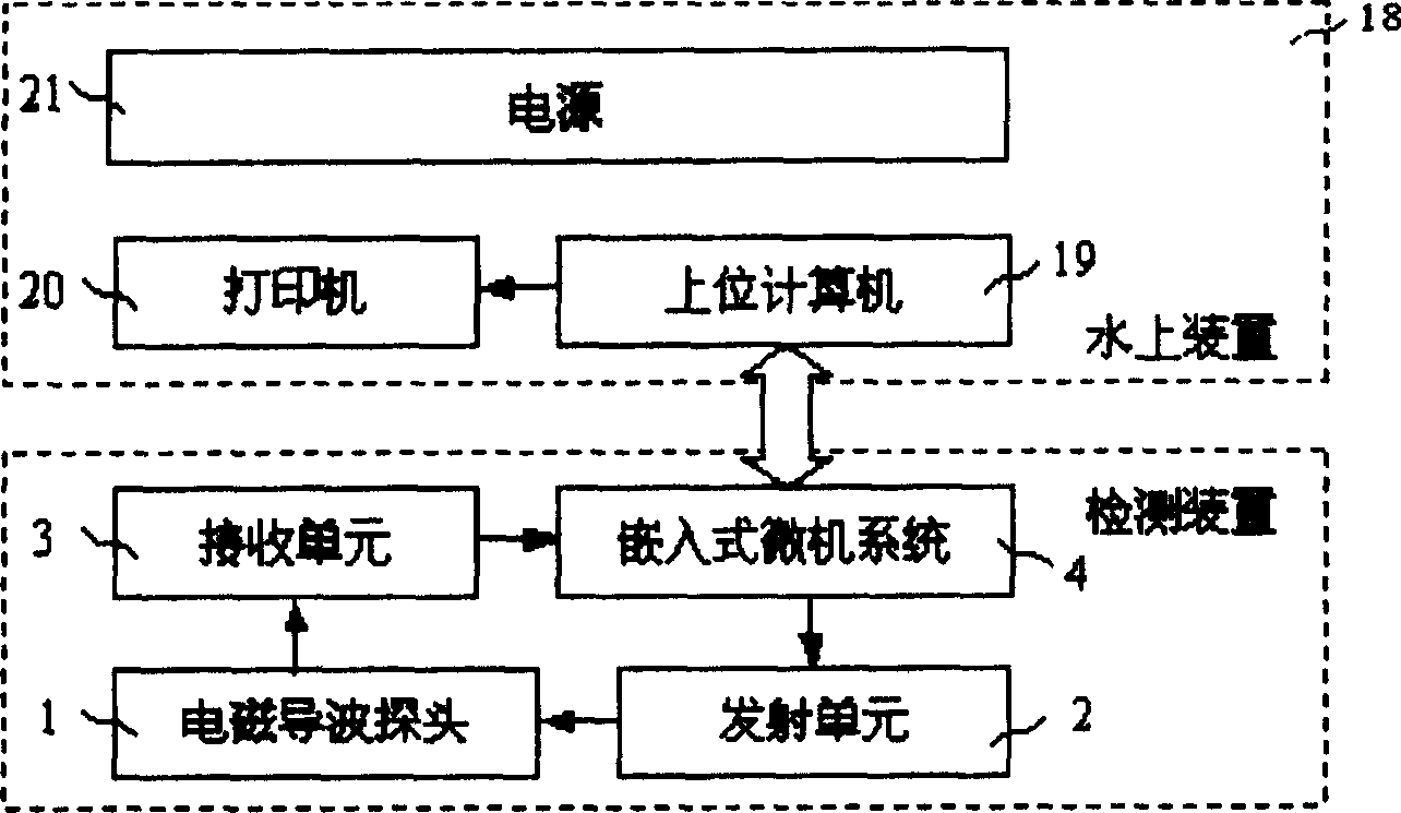
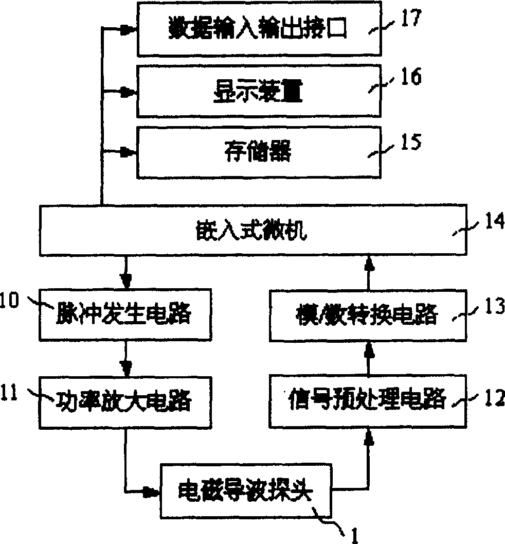
[0032] Such as figure 1 , figure 2As shown, the present invention includes: an electromagnetic guided wave probe 1 , a transmitting unit 2 , a receiving unit 3 and an embedded microcomputer system 4 . The input end of the transmitting unit 2 is connected to the embedded microcomputer system 4, the input end of the electromagnetic guided wave probe 1 is connected to the output end of the transmitting unit 2, and the output end of the electromagnetic guided wave probe 1 is connected to the input end of the receiving unit 3 , the output end of the receiving unit 3 is connected with the embedded microcomputer system 4 .

[0033] The detection device of the present invention can be carried by divers to dive into water for detection, can also be installed on an automatic detection robot for detection, and can also be installed on a manipulator of an intelligent submersible for detection.

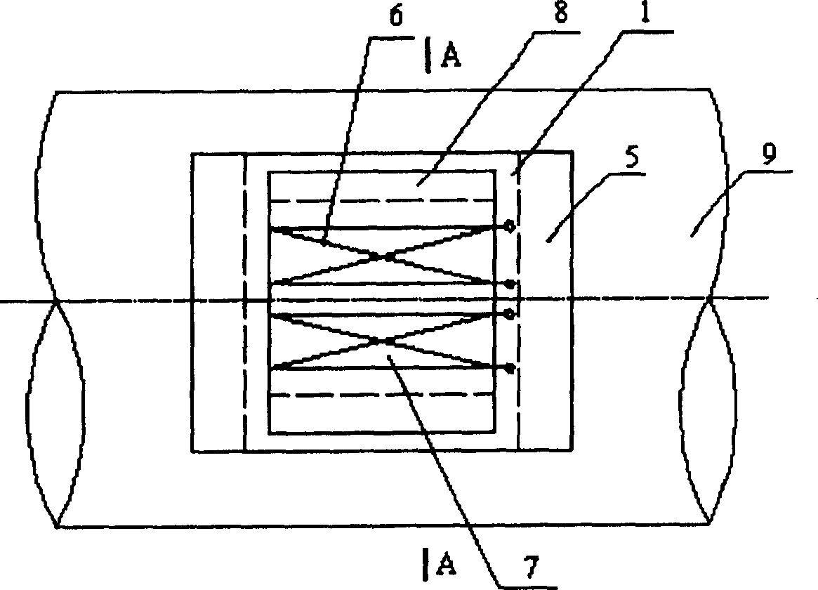
[0034] The electromagnetic guided wave probe 1 adopts a longitudinal electromagnetic guided...


PUM


Abstract

A device consists of electromagnetic guide wave probe emtting unit, receiving unit and embedded microcomputer. It is featured as setting said probe near to outside of detected pipe, generating pulse signal onto excitation coil, receiving return wave signal caused by defect, processing signal with A / D converter and inputting it to embedded microcomputer, analysing processed data and submitting out evaluation for current state and life time of the structure.

Description

technical field [0001] The invention relates to an electromagnetic guided wave detection device and method, in particular to an electromagnetic guided wave detection device and method for structural defects of an ocean platform. It is used in the technical field of detection equipment. Background technique [0002] At present, the commonly used non-destructive testing techniques for the detection of offshore platform structures mainly include underwater magnetic particle testing, underwater AC magnetic field testing, underwater ultrasonic testing and underwater ray testing. Underwater magnetic particle inspection technology uses the magnetic flux leakage phenomenon generated by the interaction between the excitation magnetic field and defects to detect defects on the surface or near the surface of the material. It relies on the accumulation of magnetic particles to indicate the existence of defects. It is mainly used for fatigue cracks, stress For the detection of corrosion...

Claims


Application Information

Patent Timeline
Patent Type & Authority Patents(China)
IPC IPC(8): G01N29/04G01N27/00G01N27/82
Inventor 金建华
Owner SHANGHAI JIAOTONG UNIV
Why Eureka
Try Eureka