Capacitor device in AC generator and mfg. method thereof

A technology of alternator, manufacturing method, applied in the field of capacitor devices, capable of solving problems such as poor insulation, longer manufacturing time, and peeling

Inactive Publication Date: 2006-10-11
MITSUBISHI ELECTRIC CORP
View PDF2 Cites 0 Cited by
  • Summary
  • Abstract
  • Description
  • Claims
  • Application Information

AI Technical Summary

Problems solved by technology

[0009] Therefore, since the resin part 72 and the filling resin 73 of the brush holder 70 have different thermal expansion coefficients and thermal contraction rates, there is a gap between the resin part 72 and the filling resin 73 due to the increase in ambient temperature and the heat from other heat generating parts. Delamination occurs, and poor insulation occurs due to the entry of salt water, etc.
[0010] In addition, in order to fix the capacitor element 35, it is necessary to fill the filling resin 73 in the capacitor housing portion and to harden the filling resin 73, resulting in a long production time.

Method used


Image

  • Capacitor device in AC generator and mfg. method thereof
  • Capacitor device in AC generator and mfg. method thereof
  • Capacitor device in AC generator and mfg. method thereof

Examples


Embodiment Construction

[0047] Hereinafter, embodiments of the present invention will be described with reference to the drawings.

[0048]

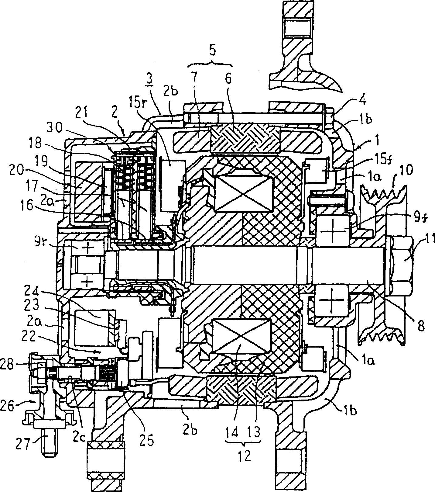
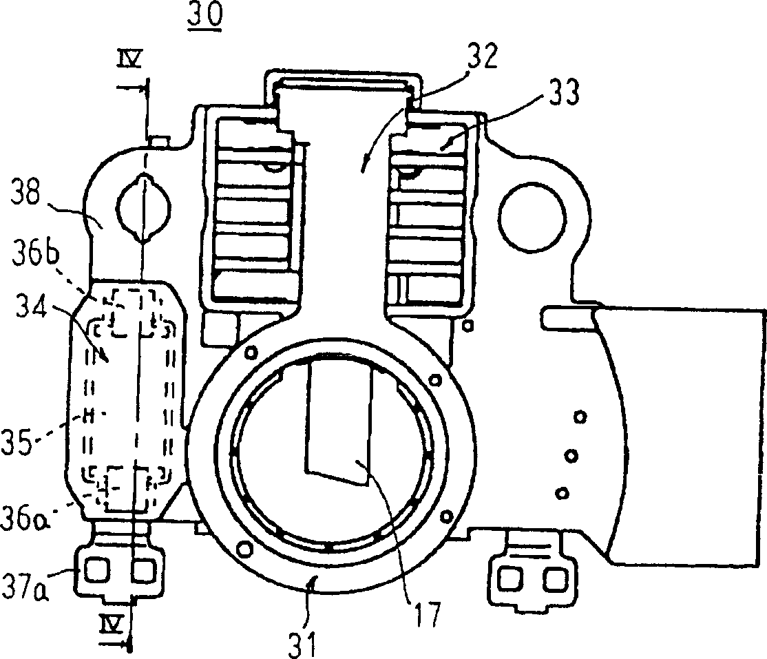
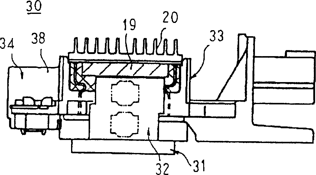
[0049] figure 1 is a longitudinal sectional view showing an alternator equipped with a capacitor device according to Embodiment 1 of the present invention, figure 2 It is a front view of the capacitor device of the alternator according to Embodiment 1 of the present invention seen from the front side, image 3 It is a side view showing the capacitor device of the alternator according to Embodiment 1 of the present invention, Figure 4 yes figure 2 Sectional view of IV-IV direction, Figure 5 It is a process drawing explaining the manufacturing method of the capacitor|condenser device of the alternator which concerns on Embodiment 1 of this invention.

[0050] figure 1 Among them, the generator casing 3 is a structure in which an aluminum front bracket 1 and a rear bracket 2 are combined into a palm shape, and are fastened and integrated by through bo...


PUM


Abstract

A capacitor device for an alternator and a method for manufacturing the same, in which a positive terminal (36a) and a negative terminal (36b) of the capacitor are respectively connected to The capacitor element (35) is integrally molded in a state where the positive terminal (37a) and the negative terminal (37b) are caulked together. At this time, the capacitor element (35) is embedded in the first resin part (38). The present invention can suppress insulation failure caused by entry of salt water and the like, and can shorten manufacturing time.

Description

technical field [0001] The present invention relates to a capacitor device for an alternator in which a capacitor element is provided in an inner space of a generator housing and a method for manufacturing the same. Background technique [0002] Conventionally, in an alternator, a capacitor element is connected in parallel with the positive and negative poles of the alternator, mainly to absorb the surge generated by the rectifier and to prevent noise such as sound from propagating to the vehicle electrical load device. [0003] The capacitor element is housed in a bottomed cylindrical capacitor container, and is integrated with the capacitor container by filling the capacitor container with hardened filling resin. Then, the capacitor container containing the capacitor element is inserted into the insertion hole pierced in the brush holder as the rear side built-in mold, and the element side terminal is joined to the holder side terminal by joining means such as soldering. ...

Claims


Application Information

Patent Timeline
Patent Type & Authority Patents(China)
IPC IPC(8): H02K19/16H02K11/00H02K5/14H02K11/02H02K11/04H02K13/00H02K13/14H02K15/02H02K19/36H02K25/00
CPCH02K5/141H02K11/026Y10T29/49009Y10T29/49172Y10T29/49169Y10T29/43H02K11/05H02K11/028H02K25/00H02K11/049
Inventor 大桥笃志浅尾淑人森角英规
Owner MITSUBISHI ELECTRIC CORP
Why Eureka
Try Eureka